
Motor Mechanism
Introduction
The diagrams are shown with circuits de-energized, all devices open, connected, and charged, and relays in normal position.
After tripping initiated by the push-to-trip button or by the MN undervoltage trip release or the MX shunt trip release, circuit breaker reset can be:
o automatic
Following tripping due to an electrical fault (with an SDE contact), reset must be carried out manually.
Motor Mechanism (MT) With Reset
Motor mechanism wiring diagrams:
Communicating Motor Mechanism (MTc)
Opening, closing and reset orders are transmitted via the communication network. The Enable automatic reset and Enable reset even if SDE parameters must be set using EcoStruxure Power Commission software via the screen, by clicking the blue text.
Auto/manu is a switch on the front of the motor mechanism.
DOCA0140EN-01
© 2020 Schneider Electric. All rights reserved.

Galvin Power is reader-supported. When you buy via our links, we may earn a commission at no cost to you. Learn more

What is a Shunt Trip Breaker and How Does It Work?
Written by Edwin Jones / Fact checked by Andrew Wright

What is a shunt trip breaker? Does it add protection to your electrical system?
The shunt trip breaker is a combination of the shunt trip accessory and the main circuit breaker. This installs on the main breaker to add protection to your electrical system. This adds security to your electrical system as it manually or automatically cuts the electric supply in your circuit.
This accessory can help prevent short circuits and avoid electrical damage should a disaster occur in your home.
Let me tell you more about the shunt trip breaker to help you decide if you need additional protection for your electrical system.
Table of Contents
What is Shunt Trip Breaker and How Does It Work
Where are shunt trip breakers most used, how to install a shunt trip accessory to the breaker.

You should know that shunt trip breakers are different from GFCI circuit breakers.
The GFCI circuit breaker contains one big white tail wire for neutral connections only. It cannot be connected to any control package because the GFCI circuit breaker is solely designed to detect a sudden electrical surge. It has no other purpose but to cut power in case of a short.
Meanwhile, the shunt trip breaker wiring comprises two wires. One connected to the ground, and another to a control system. The control system can be connected to a sensor or to a manual switch. When activated, the shunt trip accessory will cause the main breaker to trip.
For example, if you install a shunt trip with a smoke detector, it will activate and cut off the power should the smoke sensor trigger. It can also be installed with a remote switch , allowing you to trip your breaker manually.
It is crucial to know the difference between a regular circuit breaker and a circuit breaker installed with shunt trip accessories.

The shunt trip definition means that it is a way to cut off electrical power through other sensors, not just via thermal activation. Since this is an optional accessory for a circuit breaker, it is not required for a home electrical system.
However, it is recommended for added safety. This is especially true if you’re working with industrial machinery. Furthermore, you can use it as a manual emergency switch to shut down your main breaker.
Before installing a shunt trip, consider its cost and your existing system. You may need to change the breaker panel and circuit breakers, especially if it is not compatible with shunt trips. You may also need a new line to connect the remote emergency switch to your breaker box.
Generally, most commercial kitchens, elevators, and offices have this shunt trip breaker because it is required. Commercial kitchens use this device in compliance with ANSI/ASME CSD-1, while elevators and escalators comply with ASME A17.1. These codes refer to the controls and safety standards provided by ASME’s.
This question is a topic of discussion among Reddit members as well. Join the conversation here:
Found at a dominos by u/Guilty_Sympathy_496 in electricians
Mostly, installing a shunt trip relay requires that the breaker and the shunt be from the same maker. Also, not all breaker models are compatible with this accessory.
Once you’re sure that your system can take a shunt trip accessory, installation is pretty much straightforward. You can watch this video by Aaron CBIONE for some tutorials.
Note: Every circuit breaker comes with different instructions. It would depend on the brand and model of the breaker .
However, the critical part of every installation is that you need to connect the shunt to your sensor. You may need a shunt trip breaker diagram as a reference to ensure correct installation.
Also, check the brand and model of your breaker before proceeding with the installation. Some makers only allow a factory install of the shunt trip and other accessories. DIY installation may void the warranty of your breakers. It’s best to read up on the manual or consult an electrical professional before making any changes.
What is a shunt trip breaker? The shunt trip is an optional accessory for a circuit breaker for added protection to your system. It is designed to connect to a secondary sensor. It will trip the breaker automatically if the sensor is triggered. It can also be activated via a remote switch that you can install.
Do you think that a circuit breaker is enough to protect your investment? Or do you want an additional layer of protection for your electrical circuit? If you’re not decided yet, reach out to me in the comments section below, and I will be happy to help you.

I am Andrew Wright. With 8 years of experience designing, installing, and maintaining electrical power systems. I love my job, and I have always wanted to offer others the necessary help so they can take care of their houses.
Your Favorites is empty.
- Manufacturers
Fault diagnosis and maintenance of air circuit breaker
From: Quisure 2020-10-27
There are many air circuit breakers in the distribution equipment of high-rise buildings, which are generally used as low-voltage main switch or branch circuit switch with large capacity, which plays a very important role in the power supply system. Once the fault occurs, it will cause large-area power failure and economic loss. The following through the maintenance work of some examples to illustrate the air circuit breaker operation fault analysis and treatment methods.
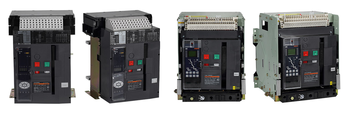
Nader Air circuit breakers(ACBs)
Air circuit breaker tripped and reclosing failed
1. firstly, determine whether the air circuit breaker is non accident trip.
Non accident trip refers to tripping without short circuit and overload fault. There are many reasons why the air circuit breaker can not be closed. First of all, it is necessary to determine whether the trip is caused by the short circuit and overload of the circuit, or due to the fault of itself or the control circuit. The following are the steps and methods to find and determine whether it is a line fault or an air circuit breaker fault.
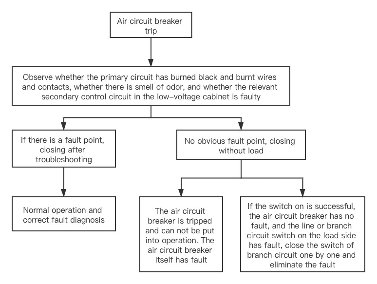
After it is determined that it is the fault of air circuit breaker, check it after pulling out (drawer type air circuit breaker).
2. Air Circuit Breaker Common Troubleshooting
(1) Air circuit breaker cannot be closed due to the black out to the undervoltage release
Too low voltage or power failure of the undervoltage release coil will also trip the air circuit breaker and cannot reclose. The following four situations will cause the undervoltage release coil to lose power:
The fuse of protection circuit, such as RT14, is fused, causing circuit blockage and power failure of trip coil of undervoltage tripper.
Poor contacts such as closing buttons, relay contacts, auxiliary contacts of circuit breakers, etc., and damaged components may lead to circuit blockage and power failure of trip coils.
Broken wires and loose crimping screws in the circuit will also cause the circuit to be blocked and the trip coil to be disconnected.
Because the coil of under-voltage tripper is in power-up state for a long time, environmental pollution, inflexible engagement of armature or excessive air gap between iron core and armature are easy to cause excessive current, which will cause the tripping coil to heat and burn out and lose the function of tripping coil.
The above faults can be correctly judged through observation and simple inspection and testing. Therefore, once the fault is found, it should be eliminated in time. If the contact is loose, it must be tightened, the component is damaged or the coil is burned, it needs to be replaced.
(2) Failure of mechanical system causes air circuit breaker not to close
After tripping and closing several times, the operating mechanism of air circuit breaker is severely worn and the following faults may occur:
If the motor drive mechanism is worn out, such as the worm wheel and worm of the ME switch are damaged, the operating mechanism of the air circuit breaker cannot be driven to buckle and close. The replacement of worm gears and worms is complicated and requires professional maintenance.
The wear of free tripping mechanism makes it difficult to close the air circuit breaker and easy to trip. Sometimes it just barely closes. In case of vibration, it trips itself. Sometimes once closed, it trips again.
At this time, the adjusting screw should be rotated to adjust the relative position of the tripping half shaft and the tripping so that the contact area is about 2.5mm^2. Replace the corresponding parts if necessary.
Failure of energy storage spring in operating mechanism.When closing, the four-link mechanism of the air circuit breaker can not push to the dead point and the mechanism can not self-maintain in the closing position. Therefore, the air circuit breaker can not close properly, so the energy storage spring must be replaced.
Operating mechanism is inflexible and stuck.Because this type of circuit breaker is not fully enclosed, inadvertently dropping screws, nuts and other foreign bodies in the operating mechanism will cause stuck operation of air circuit breaker, which will affect closing. In addition, lack of lubricating grease in the rotating and sliding parts will cause slight deformation of the open energy storage spring of the operating mechanism and the air circuit breaker will not close. Therefore, in addition to checking for foreign bodies in the operating mechanism, lubricating grease should be injected into the rotating and sliding parts when the above faults occur.
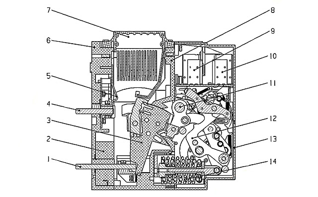
Structure of air circuit breaker
Press trip button, air circuit breaker refuses to break
The failure of the air circuit breaker to break normally may be due to the following failures.
1. Button failure
Mechanical failure of the button or poor contact of the conductor will cause the trip circuit to be blocked, which will lead to the deactivation of the shunt trip coil, the armature can not be pull in and the air circuit breaker can not be broken.
2. Shunt trip failure
The tripping of air circuit breaker is affected by open or short circuit of shunt trip coil and blockage of armature engagement. Therefore, regularly check the shunt trip, remove the obstacles affecting the armature attraction, and replace the coils with open or short circuit in time to ensure that the air circuit breaker can be quickly disconnected when the circuit needs to be disconnected.
3. Failure of trip-free mechanism
The contact surface between the tripping half-shaft and the tripping of the trip-free mechanism is too large (usually 2-3mm^2), which will make the circuit breaker refuse to breaking. Therefore, by using the adjusting screw, the tripping half-shaft can rotate at an angle to meet the requirements of the contact surface of 2-3mm^2, and the contact surface is coated with low temperature extreme grease to reduce friction and facilitate tripping.
Other faults
1. noise of undervoltage tripper.
Undervoltage tripper often produces abnormal noise after working for a period of time. Oil and dust on working surface of iron core should be removed regularly. If short circuit ring breaks, it needs to be replaced.
2. Burning out of mini-motors
Failure of the limit switch can cause the mini-motor in the electric operating mechanism to burn out. If it is necessary to close the circuit breaker with the electric operation mechanism, press the closing button, the power supply circuit of the motor will be connected, and the motor rotates. After completing the energy storage or closing of the mechanism, the power supply circuit of the micro motor should be disconnected by the limit switch. However, it cannot be disconnected due to the failure of the limit switch, which will cause the motor to overheat and burn out for a long time.
3. Short circuit due to poor insulation
The insulation performance of air circuit breaker will gradually deteriorate after long-term use. If improper maintenance is carried out in ordinary times, dust accumulation on the surface of insulating parts and moisture erosion will accelerate insulation aging, which may cause short circuit between phases or relative ground during power distribution operation or when short-circuit current is cut off.Therefore, it is necessary to keep the insulation surface clean and prevent the insulation performance from deteriorating so as to prolong the service life of the circuit breaker.
Measures required for air circuit breaker after breaking short-circuit current
After each short-circuit current cut-off, the air circuit breaker shall be checked as follows:
1. Contact system
(1) Smoke marks on the main and arc contacts are wiped off with alcohol.
(2) If small metal particles form on the contact surface, they should be cleaned and smoothed.
(3) If the thickness of silver alloy contact layer on the main contacts (dynamic and static contacts) is less than 1mm due to electric wear, it must be replaced, and the dynamic and static contacts should be replaced at the same time.
(4) Check the contact pressure spring, if it fails due to overheating, replace it in time.
(5) Check whether the flexible connection is broken or not. A few of the broken zones should be removed. If most of the zones are broken, the flexible connection should be replaced.
2. Arc Extinguishing System
(1) Clean the metal particles and soot on the wall and grids of the arc extinguishing chamber. If the grids are welded or burnt seriously, they should be replaced.
(2) If the arc extinguishing chamber is damaged, it is not allowed to be used again and must be replaced.
(3) The newly exchanged arc extinguishing chamber should be dried before use to ensure good insulation.
3. Operating mechanism and trip-free mechanism
(1) Lubricating oil can be properly filled first.
(2) Operate closing several times with electric operating mechanism and manual handle respectively. The operating mechanism should be flexible and the air circuit breaker should be closed reliably. When the switch-off button is pressed, the air circuit breaker should trip and break instantaneously.
Find more products in China
Importing from China, One-stop purchase replace a step by step learn guide.
Remaining: 500
Need technical support?
Related articles
What Is a Circuit Breaker
Circuit breaker refers to a switching device that can close, carry and break current under normal circuit conditions and can close, carry and break...
What is a Residual Current Circuit Breaker?
Residual current circuit breaker(RCCB) is a switch that can act automatically when the leakage current in the circuit exceeds a predetermined value...
What is a Buzzer?
Buzzer is a kind of voice device that converts audio model into sound signal. It is mainly used to prompt or alarm. According to different design...
What is the difference between MCCB and ACB?
Moulded case circuit breaker and air circuit breaker are very common products, but many people do not understand the difference between them...
What is an air circuit breaker?
Air circuit breaker(ACB) is a mechanical switching device which can turn on, carry and break current under normal circuit conditions, and also turn...
What is a molded case circuit breaker?
Molded case circuit breakers(MCCBs) automatically cut off current when the current exceeds the trip setting. Plastic housing refers to the housing...
What is the working principle of the buzzer?
The buzzer is a sounding device that can convert audio signals into sound signals. It is usually powered by DC voltage. It is mainly divided into...
What is the difference between MCB and RCCB?
What are the similarities and differences between miniature circuit breaker(MCB) and residual current circuit breaker(RCCB)?
Popular Articles

How does an emergency stop button work?
Emergency stop button switch is a fail-safe control switch that provides safety for the machinery and for the person using the machinery.

What is the principle of the push button switches?
We encounter various push button switches almost every day, such as medical equipment, automated production lines, and communication equipment.
What are the common faults of relays?
During the use of the relay, due to various reasons, such as poor product quality, improper use, poor maintenance, etc., various failures often occur.
What is the principle and function of the relay?
A relay is an electronic control device, which has a control system and a controlled system , and is usually used in automatic control circuits.

Popular products
Miniature Circuit Breakers
Miniature circuit breakers(MCBs) - 1pole, 2poles, 3poles, 4p...

DC Miniature Circuit Breakers
DC Miniature circuit breakers(MCBs) - 1pole, 2poles, 3poles,...

Molded Case Circuit Breaker
Molded Case Circuit Breakesr(MCCBs) - 2poles, 3poles, 4poles...

Air Circuit Breaker
Air Circuit Breakers(ACBs) - 3poles and 4poles; Rated curren...

Emergency Stop Switch
Emergency Stop Switches(E-Stops), also known emergency stop ...

Key Lock Switch
Key Lock Switches or Keylock Switches are electrical switch ...
- How to Control Motor From Two Places
- 220 Volt Single Phase Capacitor Start Motor Wiring Diagram
- Permanent Split Capacitor Motor Wiring Diagram
- Single Phase Motor Capacitor Start Capacitor Run Wiring Diagram
- Fridge Compressor Overheating And Shutting Off Problems And solutions
Electrical Online 4u – All About Electrical & Electronics
A platform to learn electrical wiring, single phase, 3 phase wiring, controlling, HVAC, electrical installation, electrical diagrams
Shunt Trip Breaker Wiring Diagram Explanation
As you know Safety is important in electricity works. Today I am writing about the shunt trip breaker wiring diagram which is related to the safety and protection of electricity. As you know that electricity is dangerous but it’s become more dangerous when it’s upgraded from 220 volts to 3 phase 440 volts. As you that mostly we use 3 phase system in industrial states where we can not protect our electrical distribution using RCD (residual current device). In Single phase wiring or house wiring, we use an electric power supply between phase and neutral which can be controlled by using a simple double pole RCD Breaker. But When it’s come to high-load places or where we use the three-phase supply then use an MCCB (module case circuit breaker) Shunt trip circuit breaker with an emergency push button switch which we know better with the name of EPO (emergency power off) button.
Shunt Trip Breaker Wiring Diagram with EPO Button.
In this post, I am just telling you about the wiring of a single EPO button with a shunt trip MCCB breaker. In an industrial state, the Electric operator’s duty is to operate the machinery and his duty is on the front of the Main panel board. Now if a short circuit is done in an electrical installation or other electrical accident, the operator can easily push a small push button switch and the all-electric power supply will be powered off. If we compare it with switching off the main circuit breaker then it will get more time.
Among the advantages of a shunt trip breaker, the most important thing is that we can install the emergency switch (EPO) anywhere, from where can easily push the button or where the push button is near to us.
One thing more is that we can install more than one EPO button for one breaker and every button will work the same. However, in this post shunt trip breaker wiring diagram I show only one EPO button and INSHALLAH in the next post I will show you the installation of multi EPO (emergency power off) buttons for a single shunt trip MCCB breaker.
Also, read below How do wire 3 or 4-pole MCCB Breakers? How to wire RCD Breaker? How earthing system works?
How Shunt Coil Work
In simple words, a shunt trip is an electromagnetic coil which makes a magnetic field by providing an external power source. In the coil a moveable rod is fixed with a spring and when we provide the supply The shunt trip moveable rod hit the tripping point or disconnecting point of the circuit breaker internally and the breaker becomes off or trips.
In the MCCB circuit breaker, we have a pushable button or place which is named “push to the trip” and when we switch on the breaker and push this button the breaker becomes switched off and trips due to pushing this button. The shunt trip coil rod pushes this point internally when the shunt coil is operated.
Here are some images of shunt coils and after that, we will discuss the shunt trip breaker wiring diagram with an image + symbol diagram.
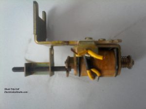
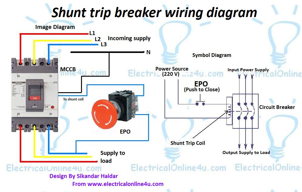
Now let’s how to wire the shunt trip device (accessory), it’s too simple as I have shown in the above shunt trip device images that a shunt coil has only two wires, just like a magnetic contactor or magnetic relay coil. But you must provide the power source regarding coil-rated volts. You can find out the rate coil label on the shunt coil, circuit breaker or on the shunt trip coil.
But the question is how to wire it. And the answer is that “it’s also too simple”. We use a push button switch for the shunt coil which we know by its short name “EPO” which I discuss in my above words. In the EPO switch, we have four terminals of which two are Normally close to each other and the other two are normally open. So we need to provide the supply / current to the shunt trip device circuit breaker when the emergency moments come.
I.e example ” if we have a shunt trip coil which operates on 220 volts, so we need to provide the 220 volts AC current to the shunt trip coil to operate or to trip the breaker in an emergency time. So our neutral will be connected directly to the shunt tripping coil and Phase (hot wire) will be connected to the coil another side through the EPO push button switch normally opens contacts.
So the EPO switch will be normally open and when we push the switch in emergency time the switch normally opens contacts will make a close contacts connection and the hot wire current start flowing to the coil and complete the circuit because the neutral wire current is already connected to the coil. So the coil will make a magnetic field and push the rod, the rod will press the trip point and the breaker will disconnect the power supply to load.
Here is the complete explanation of the shunt trip circuit breaker wiring diagram which helps you understand completely.

What is the purpose of a shunt trip circuit breaker
The main purpose of a shunt trip breaker is that we can easily switch off the main circuit breaker from our nearest place in a short time and can save us from electrical accidents.
Final words To wire, a shunt tripping breaker follows the below steps.
- First of all wire your Circuit breaker.
- Then connect the neutral wire to the shunt trip coil.
- Then connect the Phase (hot wire) to the EPO button normally open contact.
- Then get a connection from EPO to another side of the normally open contact and connect to the shunt trip coil.
- ← What’s Capacitor and Construction – Symbol Diagram
- How To Check Compressor Windings With Multimeter →
You May Also Like
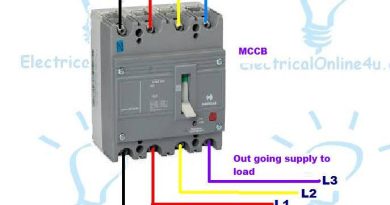
3 Pole – 4 Pole MCCB Wiring Diagrams and Installation
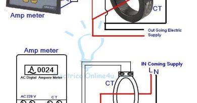
Digital Ammeter Wiring With Current Transformer – CT Coil

Voltmeter Selector Switch Wiring 3 Phase 4 Wire System
3 thoughts on “ shunt trip breaker wiring diagram explanation ”.
Hi, I have a three phases circuit breaker, with 4 incoming cables and 4 cables to load (even the N cable is connected through the circuit breaker). Is it correct to connect the shunt trip to the phase and N in the load side of the circuit breaker?
thanks this is good blog. https://krmlight.com/shunted-vs-non-shunted/
One thing more that we can *install more *than* one EPO *button.
Leave a Reply Cancel reply
Your email address will not be published. Required fields are marked *
Save my name, email, and website in this browser for the next time I comment.
- Introduction
- Codes and Standards
- Features and Benefits
- MasterPact NW Circuit Breaker Design
- MasterPact NW Cradle Design
- MasterPact NW with ArcBlock<span><span><span style="font-family: Arial; ">™</span></span></span> Technology
- MasterPact NT Circuit Breaker and Cradle Design
- Correction Factors
- Shipping Weights
- MasterPact Circuit Breakers with MicroLogic Trip Units
- Power Meter Functions
- Display Function
- Instantaneous RMS Measurements
- Maximum / Minimum Ammeter
- Energy Metering
- Demand and Maximum Demand Values
- Power Quality
- Contact Wear
- Circuit Breaker Load Profile
- Management of Installed Devices
- Display of MicroLogic Trip Unit Measurements and Alarms
- Status Indications and Remote Control
- Main Characteristics
- Communication Components and FDM121 Connections
- Display of MicroLogic Trip Unit Measurements and Trips
- Status Indications
- Remote Control
- Communication Components and FDM128 Connections
- Thermal Imaging
- Ammeter (A) Trip Unit Without 24 Vdc Power Supply at F1 and F2
- Ammeter (A) Trip Unit With 24 Vdc Power Supply at F1 and F2
- Power (P) and Harmonic (H) Trip Unit Without 24 Vdc Power Supply at F1 and F2
- Power (P) and Harmonic (H) Trip Unit With 24 Vdc Power Supply at F1 and F2
- True RMS Current Sensing
- Protection Settings
- Ammeter Measurements
- Communication Network
- Configuring Alarms and Other Protection Functions
- Maintenance Record
- Load Shedding and Reconnection Parameters
- Indication Option via Programmable Contacts
- Trip and Alarm Histories
- Waveform Capture
- Customized Alarm Programming
- Additional Technical Characteristics for Type P and Type H Trip Units
- Long-Time Trip Functions
- Short-Time Trip Functions
- Instantaneous Trip Function
- Ground-Fault Trip Functions
- Wiring System ULP
- Four Functional Levels
- Modbus Principle
- Ethernet Principle
- COM Option in Masterpact Circuit Breakers
- IFE Interface, IFE Interface + Gateway Description
- 24 Vdc Power Supply
- Required Circuit Breaker Communication Modules
- Characteristics
- Technical Characteristics
- Simplified IFM Installation
- Description
- IO (Input/Output) Application Module for Low-Voltage Circuit Breaker Resources
- Pre-Defined Application
- User-Defined Applications
- Application Rotary Switch
- Setting Locking Pad
- Compatible Devices (Configuration and Device Management)
Options for Remote Operation
Spring-charging motor (mch).
Shunt Trip (MX1) and Shunt Close (XF)
Additional Shunt Trip (MX2) or Undervoltage Trip (MN)
Time-delay module for undervoltage trip.
Ready-to-Close Switch (PF)
Electrical Closing Push Button (BPFE)
Remote reset (res) and automatic reset after fault trip, auxiliary switch (of).
Overcurrent Trip Switch (SDE)
Connected Closed Switch (EF)
Cradle position switch.
External Neutral Current Transformer (CT)
External Sensor for Source Ground-Return (SGR) and Modified Differential Ground-Fault (MDGF) Protection
Metering current transformers (cts), voltage measurement inputs, sensor plugs, adjustable rating plugs.
External Power Supply Module
External Battery Backup Module
M2C/M6C Programmable Contact Modules
Zone-selective interlocking (zsi).
Restraint Interface Module (RIM)
Cradle Connections
Hand-Held Test Kit
Full-Function Test Kit
Lockable Push Button Cover
Open position padlock and key lock provisions, disconnected position locking, door interlock (vpec), racking interlock between racking handle and off position (ibpo), cable door interlock kit, source changeover interlocks, open door racking interlock (vpoc), automatic spring discharge mechanism (dae), cradle rejection kits, rail padlocking.
Mechanical Operation Counter (CDM)
Shutter and Shutter Lock
Door escutcheon (cdp), transparent cover (ccp) for door escutcheon, masterpact nw remote racking device.
- Wiring Diagrams for MasterPact NW Circuit Breakers
- Wiring Diagrams for MasterPact NT Circuit Breakers
- Additional Wiring Information for MasterPact NW NT Circuit Breakers
- MasterPact NT Enclosure Information
- UL<span><span><span style="font-family: Arial; "> ® </span></span></span> and ANSI Three-Pole Drawout Circuit Breakers
- UL and ANSI Three-Pole Fixed Circuit Breakers
- UL and ANSI Four-Pole Drawout Circuit Breakers
- UL and ANSI Four-Pole Fixed Circuit Breakers
- IEC Three-Pole Drawout Circuit Breakers
- IEC Three-Pole Fixed Circuit Breakers
- IEC Four-Pole Drawout Circuit Breakers
- IEC Four-Pole Fixed Circuit Breakers
- Neutral Current Transformers
- Enclosure Information
- UL<span><span><span style="font-family: Arial; "> ® </span></span></span>/ANSI Three-Pole Drawout Circuit Breakers
- UL/ANSI Three-Pole Fixed Circuit Breakers
- UL/ANSI Four-Pole Drawout Circuit Breakers
- UL/ANSI Four-Pole Fixed Circuit Breakers
- Accessory Dimensions
- Overview of Selection Procedure
- T-Frame Circuit Breaker Selection
- T-Frame Switch Selection
- W-Frame Circuit Breaker Selection
- W-Frame Switch Selection
- Y-Frame Circuit Breaker Selection
- Y-Frame Switch Selection
- MicroLogic 6.0 A/P/H Trip Units
- MicroLogic 5.0/6.0 A/P/H Trip Unit
- MicroLogic 3.0 Trip Units
- MicroLogic 2.0A Trip Unit
- Instantaneous Override Values No. 613.10
- MasterPact NW/NT Low Arc Flash Circuit Breakers
For the best experience of this site, please enable Javascript for the www.productinfo.schneider-electric.com domain.
Accessories
Two options are available for remote operation of MasterPact circuit breakers: direct connection or a communication network.
The wiring diagrams for these two options are shown below.
Wiring Diagram for Remote ON/OFF Function by Direct Connection
Remote Operation Accessories
Masterpact circuit breaker equipped for remote on/off function cluster shield is not shown.
The remote ON/OFF function is used to remotely open and close the circuit breaker. It is made up of the following components:
A spring-charging motor (MCH) equipped with a spring-charged limit switch; see Spring-Charging Motor (MCH) or more information.
A shunt close (XF); see Shunt Trip (MX1) and Shunt Close (XF) or more information.
A shunt trip (MX1); see Shunt Trip (MX1) and Shunt Close (XF) for more information.
Optionally, the function may be completed with:
A ready-to-close contact (PF).
An electrical closing push button (BPFE).
A remote reset following a fault (RES).
The remote operation function may be completed with:
Auxiliary contacts (OF).
Overcurrent trip switch (SDE).
Terminal Characteristics
The spring-charging motor automatically charges the spring mechanism for closing the circuit breaker and also recharges the spring mechanism when the circuit breaker is in the ON position. Instantaneous reclosing of the circuit breaker is thus possible following circuit breaker opening. The spring-mechanism charging handle is used only as a backup if auxiliary power is absent.
The spring-charging motor is equipped as standard with a limit switch contact (CH) that signals the charged position of the mechanism (springs charged).
Spring-Charging Motor Characteristics
Maximum Wire Length—The inrush currents for these devices are approximately 200 VA. When low supply voltages (12, 24 or 48 V) are used, the maximum allowable wire length is dependent on the voltage and the wire size.
Maximum Wire Length
Shunt Trip (MX1): When energized, the shunt trip instantaneously opens the circuit breaker. The shunt trip may be energized continuously or intermittently.
Shunt Close (XF): Remotely closes the circuit breaker if the spring mechanism is charged.
Communication versions of the MX1 and XF are available for direct connection via the circuit breaker communication module (BCM ULP).
Shunt Trip and Shunt Close Characteristics
Second Shunt Trip (MX2)
This function opens the circuit breaker via an electrical order.
It is made up of:
Shunt trip (MX2, second MX) or,
Undervoltage trip (MN)
As shown in the wiring diagram for the remote tripping function below, the delay unit (installed outside the circuit breaker) may be disabled by an emergency off button to obtain non-delayed opening of the circuit breaker.
When energized, the shunt trip (MX1 or MX2) instantaneously opens the circuit breaker.
The undervoltage trip (MN) instantaneously opens the circuit breaker when its supply voltage drops to a value between 35% and 70% of its rated voltage.
If the undervoltage trip is not energized, it is impossible to close the circuit breaker, either manually or electrically. An attempt to close the circuit breaker produces no movement of the main contacts. Closing is allowed when the supply voltage of the undervoltage trip reaches 85% of rated voltage.
Undervoltage Trip Characteristics
Wire diagram for the remote tripping function.
Time-Delay Module for Undervoltage Trip (MN)
To eliminate circuit breaker nuisance tripping during temporary voltage dips (micro-breaks), operation of the undervoltage trip (MN) can be delayed. This function is achieved by adding an external delay unit (either adjustable or non-adjustable) to the undervoltage trip (MN) circuit.
Time-Delay Module Characteristics
The ready-to-close position switch indicates that the following conditions are met and the circuit breaker can be closed:
The circuit breaker is open.
The closing springs are charged.
There is no standing closing or opening order.
Ready-to-Close Switch Characteristics
Located on the front panel of the circuit breaker, this push button carries out electrical closing of the circuit breaker, taking into account all of the safety functions that are part of the control/monitoring system of the installation. The push button is installed on the control circuit of the shunt close, and connects to the communicating shunt close module (XF-COM). Terminal A2 of XF-COM is used to remotely close the circuit breaker.
Remote reset (RES): following tripping, the remote reset (RES) resets the overcurrent trip switch (SDE) and the mechanical indicator. (Voltage rating: 110/130 Vac and 200/240 Vac.) RES is not compatible with an additional overcurrent trip switch (SDE2).
Automatic reset after fault-trip: following tripping, a reset of the mechanical indicator (reset button) is no longer required to enable circuit breaker closing (factory adjustable only).
Switches and Switch Accessories
The rotary-type auxiliary switches are directly driven by the trip mechanism when the minimum isolation distance between the main circuit breaker contact is reached.
Auxiliary Switch Characteristics
Circuit breaker tripping due to a fault is signalled by a red mechanical fault indicator (reset) and one overcurrent trip switch (SDE).
Following tripping, the mechanical indicator must be reset before the circuit breaker may be closed. An additional overcurrent trip switch (SDE2) is supplied as an option and is not compatible with the remote reset (RES).
Overcurrent Trip Switch Characteristics
Connected/Closed Switch (EF) NW only
This switch combines the “device connected” and “device closed” information to produce “circuit closed” information. The connected/closed switch (EF) is supplied as an option and must be used with an additional auxiliary switch (OF) and fits into its connector (it is not available for ring terminals).
Connected/Closed Switch Characteristics
Cradle Position Switch (CE, CD, CT)
Three series of optional auxiliary switches are available for the cradle:
Cradle position switches to indicate the connected position (CE).
Cradle position switches to indicate the disconnected position (CD). This position is indicated when the required clearance for isolation of the power and auxiliary circuits is reached.
Cradle position switches to indicate the test position (CT). In this position, the power circuits are disconnected and the auxiliary circuits are connected.
Cradle Position Switch Characteristics
Possible ring-terminal combinations.
Additional Actuators for Cradle Position Switches on MasterPact NW Circuit Breakers
A set of additional actuators may be installed on the cradle to change or add the functions of the cradle position switches. Each standard actuator can be replaced by any other actuator to change the function of the cradle position switch.
MicroLogic Trip Unit Accessories
The sensor is installed on the neutral conductor for neutral protection and metering and residual current ground-fault protection for equipment.
For SGR System: The sensor is installed around the connection of the transformer neutral point to ground and connects to the MicroLogic 6.0A, 6.0P or 6.0H trip units. SGR requires a modified differential ground-fault (MDGF) sensor and MDGF interface module to connect to the trip unit.
For MDGF System: An MDGF sensor is installed on each phase and neutral of each circuit breaker and connects to the MicroLogic trip unit through an MDGF module. See MDGF Instruction Bulletin 48049-182.
Toroidal Current Transformers (CTs) for W-Frame Circuit Breakers
Metering current transformers are optional and are mounted on the NW UL or ANSI cradle. They permit connection to the standard metering device. All metering transformers are accurate with the 0.3% accuracy class, 5 A output ratio at full load (for example, a 1600 A metering CT would send 5 A at the full load of 1600 A). A standard wiring harness is also included for factory-installed MCTs. Not available for neutral pole on a four-pole circuit breaker. Not available on cradles with ArcBlok technology.
Voltage measurement inputs are required for power measurements. As standard, the trip unit is supplied by internal voltage measurement inputs placed on the bottom terminals of the circuit breaker. On request, the internal voltage measurement inputs may be replaced by an external source.
Sensor Plug
Sensor plugs (standard) are used to set the sensor rating (I n ) of the circuit breaker, are field replaceable and are offered at 50–100% of frame rating. For a complete list of available sensor plugs see selection information in Selection .
Adjustable Rating Plug
Eight interchangeable rating plugs are available to limit the long-time threshold setting range for greater versatility.
Adjustable Rating Plug Settings
Power supply modules are available in six input voltages: 24/30 Vdc, 48/60 Vdc, 125 Vdc, 110/130 Vac, 200/240 Vac, and 380/415 Vac (all +10%, -15%). The output voltage for each is 24 Vdc; the output power is 5 VA/5 W (ripple < 5%). The modules are not UL Listed.
When used with the MicroLogic A, P, and H trip units, a power supply module makes it possible to:
Display currents less than 20% of sensor (I n ).
Maintain display of tripping causes after opening of the circuit breaker (P and H trip units only).
Store the value of the interrupted current (P and H trip units only).
Power the M2C module (P and H trip units only).
The external battery backup module provides up to 12 hours of backup power for the power supply module.
These contacts are used with the MicroLogic P and H control units, and indicate the type of fault and instantaneous or delayed threshold overruns (i.e trip unit protection pick-up, current/voltage unbalance, under/over voltage, reverse power, phase rotation, under/over frequency, and load shedding). The M2C unit is powered from the control unit’s 24 Vdc source (100 mA consumption); the M6C unit requires an external 24 Vdc power supply (100 mA consumption).
They are programmed via the control unit using a keypad or via a supervisory station with the COM communication option. They may be programmed:
with instantaneous return to the initial state;
without return to the initial state;
with return to the initial state following a delay.
Characteristics for M2C/M6C Programmable Contacts
Zone-selective interlocking (ZSI) is used to reduce the stress on electrical distribution equipment during fault conditions by reducing the time it takes to clear the fault, while maintaining system coordination between overcurrent protective devices.
During a short-circuit or ground-fault condition on a ZSI system, the device directly ahead of the fault sends a signal upstream via control wiring to restrain upstream circuit breakers from tripping and then trips with no intentional time delay to clear the fault. Upstream devices which receive a restraint signal obey their short-time and/or ground-fault delay settings to maintain coordination in other areas of the system. Upstream devices that do not receive a restraint signal trip with no intentional time delay.
For ZSI to work, trip settings must be coordinated so a downstream circuit breaker will trip before an upstream circuit breaker under overload, short-circuit or ground-fault conditions. (Effective coordination requires a system coordination study.)
Example of Zone-Selective Interlocking
Fault 1—The upstream circuit breaker (A) will clear the fault with no intentional delay, regardless of its time-delay setting.
Fault 2—Circuit breaker (B) will inform upstream circuit breaker (A) that it is clearing the fault. This will prevent circuit breaker (A) from tripping instantaneously. Circuit breaker (A) will trip at the end of its time delay setting if the fault is not cleared during this time.
The restraint interface module (RIM) is used to allow zone-selective interlocking communications between circuit breakers with old Square D MicroLogic, Merlin Gerin™, or Federal Pioneer™ trip units and GC series ground-fault relays.
Downstream circuit breakers with MicroLogic 2.0A, 5.0A, 5.0P, 5.0H, 6.0A, 6.0P, and 6.0H trip units can restrain up to 15 upstream circuit breakers with MicroLogic 5.0A, 5.0P, 5.0H, 6.0A, 6.0P and 6.0H trip units without requiring a restraint interface module. If the number of upstream circuit breakers exceeds 15, then a RIM is required.
RIM Requirements (R Denotes that a Restraint Interface Module (RIM) is required.)
Masterpact nw ul listed/ansi certified 3p/4p drawout circuit breakers (rear connections), masterpact nw ul listed/ansi certified 3p/4p drawout circuit breakers (front connections), masterpact nw ul listed/ansi certified 3p/4p fixed circuit breakers (rear connections), masterpact nw ul listed/ansi certified 3p/4p fixed circuit breakers (front connections), masterpact nw iec rated 3p/4p drawout circuit breakers, masterpact nw iec rated 3p/4p fixed circuit breakers, masterpact nt ul listed/ansi certified 3p/4p fixed and drawout circuit breakers, masterpact nt iec rated 3p/4p fixed and drawout circuit breakers, test equipment.
The hand held test kit may be used to:
Verify trip unit operation, the mechanical operation of the circuit breaker, and the electrical continuity of the connection between the trip solenoid and the trip unit.
Supply control power to the trip unit for settings via the keypad when the circuit breaker is open (MicroLogic type A, P or H trip units).
Inhibit thermal imaging for primary injection test (MicroLogic type A, P or H trip units).
Inhibit ground fault for primary injection test (MicroLogic type A, P or H trip units).
- Self-restrain zone-selective interlocking (ZSI).

The full-function test kit can be used to verify LSIG functionality.
Can be used to check trip unit operation, for example:
- Operating tests on the electronic component.
- Automatic and manual tests on protection functions (trip curve verification).
- Tests on the zone-selective interlocking (ZSI) functions.
- Inhibit thermal imaging for primary injection testing.
Can also be used to:
- Check mechanical operation of the circuit breaker.
- Check the electrical continuity of connection between the trip solenoid and the trip unit.
- Print the trip unit and circuit breaker test report when used in conjunction with a PC FFTK report generator software (cat. no. FFTKRPT-V1-0) is required.
Circuit Breaker Locking and Interlocking
A transparent cover blocks access to the push buttons used to open and close the device. It is possible to independently lock the opening button and/or the closing button. The push buttons may be locked using:
One to three padlocks: 3/16 to 5/16 in. (4.8 to 7.9 mm) diameter, not supplied
Open Position Key Lock (NW)
Open Position Padlock Provision (NW)
The circuit breaker is locked in the off position by physically keeping the opening push button pressed down using one of the following:
One to three padlocks: 3/16 to 5/16 in. (4.8 to 7.9 mm) diameter, not supplied.
Key locks: One or two Kirk ® key locks (keyed alike or differently) are available for UL Listed/ANSI Certified circuit breakers; for IEC Rated circuit breakers, Ronis, Castell, or Profalux key locks are available. (MasterPact NT circuit breakers may have only one key lock on the circuit breaker.)
Keys may be removed only when locking is effective. The key locks are available in any of the following configurations:
One key lock
One key lock mounted on the device plus one identical key lock supplied separately for interlocking with another device
Two different key locks mounted on the circuit breaker for double locking
A locking kit for installation of one or two key locks may be ordered separately.
Circuit Breaker and Switch Locking Options
Cradle locking and interlocking.
Disconnected Position Locking Provisions
The circuit breaker can be locked in the disconnected position by key interlock (optional) or padlock (standard). The key interlock is on the cradle and accessible with the door locked.
Kirk key interlocks are available for UL/ANSI circuit breakers; for IEC circuit breakers, Ronis, Castell, or Profalux key locks are available. Key is captive when key interlock is unlocked.
Locking on disconnected, test, and connected positions is optional for IEC circuit breakers and standard for UL/ANSI circuit breakers.
Door Interlock (NW)
The door interlock prevents the compartment door from being opened when the circuit breaker is in the connected or test position. If the circuit breaker is put into the connected position with the door open, the door can be closed without disconnecting the circuit breaker. For greater protection, this interlock can be used in conjunction with the open door racking interlock.
The racking interlock is standard for UL and ANSI circuit breakers, and optional for IEC circuit breakers. It prevents insertion of the racking handle unless the OFF push button is pressed. Not available for IEC Rated MasterPact NT circuit breakers.
The optional cable door interlock prevents the compartment door from being opened when the circuit breaker is in the closed position. This kit includes:
Cable Door Interlock Kit Contents
Kit Contents
Source changeover interlocks allow mechanical interlocking between two or three circuit breakers (fixed and drawout).
Interlocking Two Circuit Breakers
Interlocking Two Mains Using Rods
Interlocking Two Mains Using Cables
Interlocking Three Circuit Breakers Using Cables
Interlocking Two Mains and One Generator
Interlocking Two Mains and One Tie
Interlocking Three Mains
Open Door Racking Interlock (NW)
The racking interlock prevents racking in the circuit breaker when the door is open. (Insertion of the circuit breaker racking handle is not possible when the compartment door is open.)
Automatic Spring Discharge Mechanism (NW)
The automatic spring discharge mechanism is standard for UL and ANSI circuit breakers, and optional for IEC circuit breakers. It releases the closing spring energy when the circuit breaker is moved from the disconnected position to the fully withdrawn position. Not available for IEC Rated MasterPact NT circuit breakers.
The cradle rejection feature (standard) ensures that only the properly designated circuit breaker or switch is matched with the selected cradle assembly.
Rail padlocking is standard for UL, ANSI, and IEC cradles. When used in combination with the disconnected position locking device, rail padlocking prevents the movement of the circuit breaker from the disconnected position to the fully withdrawn position when the padlock hasp is pulled out and locked.
Miscellaneous Accessories
The mechanical operation counter (CDM) registers the total number of operating cycles. One CDM is installed per circuit breaker.
The shutters automatically block access to the main disconnects when the circuit breaker is in the disconnected, test, or fully withdrawn position.
The shutter lock is used to prevent connection of the circuit breaker or to lock the shutters in the closed position.
Not available on cradles with ArcBlok technology.
These door escutcheons provide a frame and seal for the circuit breaker.
Door Escutcheons
Transparent Cover (CCP)
The cover is hinged-mounted and locked with a milled head, and is designed to be installed on the door escutcheon.
The remote racking device allows the operator to perform circuit breaker racking operations from a distance of up to 30 feet (9.1 m) away from the circuit breaker using the controller. This distance exceeds the arc flash boundary described in the arc flash safety guidelines outlined in NFPA-70E.
Show QR code for this page
Was this helpful?
Contact Information
Legal information.
The information provided in this document contains general descriptions, technical characteristics and/or recommendations related to products/solutions.
This document is not intended as a substitute for a detailed study or operational and site-specific development or schematic plan. It is not to be used for determining suitability or reliability of the products/solutions for specific user applications. It is the duty of any such user to perform or have any professional expert of its choice (integrator, specifier or the like) perform the appropriate and comprehensive risk analysis, evaluation and testing of the products/solutions with respect to the relevant specific application or use thereof.
The Schneider Electric brand and any trademarks of Schneider Electric SE and its subsidiaries referred to in this document are the property of Schneider Electric SE or its subsidiaries. All other brands may be trademarks of their respective owner.
This document and its content are protected under applicable copyright laws and provided for informative use only. No part of this document may be reproduced or transmitted in any form or by any means (electronic, mechanical, photocopying, recording, or otherwise), for any purpose, without the prior written permission of Schneider Electric.
Schneider Electric does not grant any right or license for commercial use of the document or its content, except for a non-exclusive and personal license to consult it on an "as is" basis.
Schneider Electric reserves the right to make changes or updates with respect to or in the content of this document or the format thereof, at any time without notice.
To the extent permitted by applicable law, no responsibility or liability is assumed by Schneider Electric and its subsidiaries for any errors or omissions in the informational content of this document, as well as any non-intended use or misuse of the content thereof.
© 2000 – 2019 Schneider Electric
- Get custom product tools and services
- Access training
- Manage support cases
- Create and manage your orders (authorized partners only)
Schneider Electric USA Website

CB SHUNT TRIP 100-130V AC/DC
Sustainability.
Under investigation
China RoHS declaration
Product out of China RoHS scope. Substance declaration for your information.
WARNING: Cancer and Reproductive Harm - www.P65Warnings.ca.gov
Need more information? Check our technical FAQs!
Easily find answers to the most frequently asked questions.

COMMENTS
A shunt trip device is an optional accessory in a circuit breaker that mechanically trips the breaker when power is applied to the shunt trip terminals. The power for the shunt trip does not come from within the breaker, so it must be supplied from an external source.
Three remote control solutions are provided by Masterpact MTZ devices. Wiring Basic Coils (XF, MX, MN) Masterpact MTZ circuit breakers can be opened and closed remotely by using the output contacts of a PLC or a pushbutton wired to the coils (MX, MN, XF).
Shunt trip (MX) When the shunt trip (MX) receives a pulse-type or maintained voltage within specified tolerances it signals the circuit breaker to open.
The shunt close (XF), shunt trip (MX), and undervoltage release (MN) are optional accessories mounted inside the device. They can be of standard type or diagnostic and communicating type (standard or with diagnostic function for the undervoltage release [MN]).
After tripping initiated by the push-to-trip button or by the MN undervoltage trip release or the MX shunt trip release, circuit breaker reset can be: o automatic. o remote. o manual. Following tripping due to an electrical fault (with an SDE contact), reset must be carried out manually. Motor Mechanism (MT) With Reset. Motor mechanism wiring ...
Product Description: LV429390 - MX shunt trip release, Compact NSX, 24 VDC| Schneider Electric Hong Kong, China.
This shunt trip unit for PowerPacT M- or P-Frame circuit breakers is one of the field installable accessories available. The shunt trip option allows tripping the circuit breaker from a remote location by means of a trip coil energized from a separate supply voltage circuit.
This document provides installation and removal instructions for Undervoltage Trips (MN) and Shunt Trips (MX) for use with M-frame, P-frame, R-frame and NS630b-NS3200 circuit breakers. Date: August 30 2018 | Type: Instruction Sheet
Welcome to our tutorial on wiring a Shunt Trip on QO™ Circuit Breakers. In this step-by-step guide, we'll walk you through the process of wiring a Shunt Trip in QO™ (and QOB) Circuit...
The shunt close (XF) and shunt trip (MX1) communicating voltage releases are equipped for connection to the communication module. The remote-tripping function shunt trip (MX2) and undervoltage release (MN) are independent of the communication option.
Schneider Electric's LV429387 is a shunt trip voltage release suitable for use with Schneider Electric Easypact CVS, PowerPact Multistandard and Compact NSX ranges. Voltage release type: shunt trip release; Control circuit voltage: 220 to 240V (50/60Hz), 208 to 277V (60Hz) Response time: 50ms; Supply inrush power: 30W
An under voltage release is an optional device installed in a circuit breaker that automatically triggers a power trip when the power falls below a preset level, usually between 70 and 35...
The shunt trip breaker is a combination of the shunt trip accessory and the main circuit breaker. This installs on the main breaker to add protection to your electrical system. This adds security to your electrical system as it manually or automatically cuts the electric supply in your circuit.
2. Shunt trip failure. The tripping of air circuit breaker is affected by open or short circuit of shunt trip coil and blockage of armature engagement. Therefore, regularly check the shunt trip, remove the obstacles affecting the armature attraction, and replace the coils with open or short circuit in time to ensure that the air ...
The aim of this guide is to provide users, installers, and maintenance personnel with technical information needed to operate Masterpact™ MTZ2/MTZ3 circuit breakers and switches. These devices comply with the following standards: ANSI C37 Certified Device. UL 489 Listed Device. ANSI C37.13.
NOTE: A recommended wiring schematic for the communicating style shunt trip or shunt close coils is shown below. Induced voltages in the circuit at terminal C2 and/or A2 can cause the shunt trip or shunt close to not work properly.
Green PremiumTM label is Schneider Electric's commitment to delivering products with best-in-class environmental performance. Green Premium promises compliance with the latest regulations, transparency on environmental impacts, as well as circular and low-CO 2 products.
Shunt Trip Breaker Wiring Diagram with EPO Button. In this post, I am just telling you about the wiring of a single EPO button with a shunt trip MCCB breaker. In an industrial state, the Electric operator's duty is to operate the machinery and his duty is on the front of the Main panel board.
Shunt Trip (MX1): When energized, the shunt trip instantaneously opens the circuit breaker. The shunt trip may be energized continuously or intermittently. Shunt Close (XF): Remotely closes the circuit breaker if the spring mechanism is charged.
This shunt trip is a UL Listed/CSA Certified circuit breaker accessory. Compact NSX, PowerPact Multistandard and EasyPact CVS can be equipped with either 1 MX or 1 MN auxiliary. Show more specifications. Green PremiumTM label is Schneider Electric's commitment to delivering products with best-in-class environmental performance.
A shunt trip device is an optional accessory in a circuit breaker that mechanically trips the breaker when power is applied to the shunt trip terminals. The power for the shunt trip does not come from within the breaker, so it must be supplied from an external source. Released for: Schneider Electric Australia.
Shunt trips là một cuộn dây được gắn trong máy cắt điện như VCB, ACB, MCCB hoặc bên hông của MCB. Chức năng của shunt trips là tạo ra một mạch điện phụ bên ngoài để kích hoạt thiết bị cắt điện, khi cần thiết, như trong trường hợp cần ngắt nhanh thì shunt trips sẽ ...
CB SHUNT TRIP 100-130V AC/DC. S33035. Product availability: Non-Stock - Not normally stocked in distribution facility. Find a reseller.