- Air Conditioning
- Electrician
- Garage Door Installation
- Garage Door Repair
- Heating & Furnace
- HVAC Contractors
- Landscaping
- Pest Control
- Experiences
- Homeowner Login
- Join As a Pro

What Are Thermal Magnetic Circuit Breakers?
Are you looking to hire a:.
- Carpentry Pro
- Landscaping Pro
- Plumbing Pro
- Remodeling Pro
- Roofing Pro
- HVAC Contractors Pro

Pretty much everyone is familiar with the effect of a tripped breaker in the home. Suddenly, you have no electrical power in one or more outlets and you’re forced to head down to the basement or out to the garage to switch the electrical panel back on. This usually happens when too many appliances are plugged into one outlet or connected to the same electrical circuit. That’s what triggers the circuit breaker to kick in and protect you from potential electrical hazards.
But what is a circuit breaker exactly and why is it so important in your home? Let’s take a closer look.
What is a Circuit Breaker?
We’ll start by clearing up the difference between a circuit breaker’s function and its purpose . 1. Circuit Breaker Function. The function of an electrical circuit breaker is to “break” (that is, to discontinue) a circuit of electricity. It does this automatically when it detects:
* an electrical overload -- The power demand on one of the circuits is beyond its capacity, usually because you’ve got too many items plugged in at the same time.
* a short circuit – An electrical circuit is accidentally shortened when a live wire comes in contact with another part of the circuit (usually due to faulty insulation) and takes the path of least resistance. This can result in an electrical charge in an unexpected location ... for example, a light switch.
Once the electrical issue has been resolved, the circuit breaker can then be manually or automatically set to restart the flow of electricity.
2. Circuit Breaker Purpose . The purpose of the circuit breaker is to prevent damage from occurring. An overtaxed or malfunctioning electrical system can do a lot of harm to home appliances and electronics. Much more seriously, it can endanger you and your household, with the risk of electric shock, electrocution, or electrical fire .
Circuit breakers come in varying sizes and types and may be used to protect everything from household appliances and electronic devices to high-voltage circuits which service entire cities.
Thermal Magnetic Circuit Breaker Definition
In American homes today, thermal magnetic circuit breakers are the most common type. These are circuit breakers which utilize two components to detect electrical faults.
The first component is an electromagnet that is sensitive to large surges in electrical currents. Electrical surges can cause short-circuiting, which may seriously damage your valuable electrical appliances (such as a clothes dryer or an air conditioner) or large electronics (think DVD player or desktop computer). The electromagnet responds instantly to such dangerous situations by shutting off the flow of electricity so that your appliances are protected.
The second component used in a thermal magnetic circuit breaker is a thermal bimetallic strip that responds to prolonged low-level electrical surges or overloads of electrical currents. Excessive electrical currents will heat the bimetallic strip enough to bend it towards a trip bar that turns the circuit off.
Thermal magnetic circuit breakers are popular because they can quickly limit short-circuiting and then restart the flow of electricity when the surge has passed.
Circuit Breaker Safety
- Set thermal magnetic circuit breakers according to the manufacturer’s directions for safe and effective functioning.
- Limit electrical power usage to prevent stressing your circuits. (Fringe Benefit: This tip saves money on your utility bills, as well.) Try to keep heavy-consumption electrical devices, like space heaters , irons, toaster ovens, and hair dryers, on different circuits. Avoid overloading the system with multi-outlet extension cords. If at all possible, turn off appliances and electronics when not in use.
- Install GFCI (ground fault circuit interrupter outlets ) and test them monthly.
- Rethink your existing electrical system if you have frequent tripped breaker problems. Call a licensed electrician to assess the system and make any necessary upgrades.
Related Articles

Looking for a Pro? Call us at (866) 441-6648

Electrical Average Costs
- Upgrade an Electrical Panel $1,264
- Install Outdoor Lighting $105
- Install a Smart House System $2,117
Electricians Experiences

Parking Lot Lights Restored So Employees Can Reach Cars Safely

Smoke Detector Replacement Was Done Well And Saved Us Money

Electrical Upgrade Including New Breakers And Replacement Wiring
Top cities covered by our electricians.
- Service Needed Select Service Needed Additions / Remodels / Major Renovations Air Conditioning & Heating Appliances Asphalt Paving Builders (New Home) Carpentry, Decks & Porches Carpet - Install / Clean Cleaning Services Concrete, Brick & Stone Countertops - Install / Repairs Doors Driveways, Patios, Walks, Floors Drywall Electrical / Generators Fences Flooring Garage - Build/Remodel Garage Doors, Openers Gutters Handyman Services Heating & Cooling Home Security Insulation Landscaping & Lawn Care Major Renovations Painting & Staining Pest Control / Termites Plumbing / Water Heaters / Gas Piping Recovery Services (Water, Fire, Etc) Roofing Septic System Services Siding Tile & Stone Tree Removal And Trimming Windows Other / Miscellaneous

- Circuit Breakers
- Connecticut Electric
- Crouse-Hinds Cooper
- Eaton Cutler Hammer
- Federal Pacific
- Thomas Betts
- Westinghouse
Motor Controls
- Allen Bradley
- Appleton Electric
- Cutler Hammer
- E.M. & Wiegmann
- Joslyn Clark
- Killark Electric
- Moeller Electric
- NSI Industries
Transformers
- Dongan Electric
- Hammond Power

Absolutely Everything You Need to Know About a Thermal Magnetic Circuit Breaker
- 24 Jan, 2018
- Posted by: Circuit Breaker Wholesale
Do you know how a thermal magnetic circuit breaker works?
If not, it’s worth finding out as these popular options are probably going to be the best bet for your home or building.
How a Thermal Magnetic Circuit Breaker Works
Despite the name, it’s actually fairly easy to understand how a thermal magnetic circuit breaker works. You just have to understand how two other versions operate first.
How a Magnetic Circuit Breaker Works
The main difference between these two circuit breakers comes down to what makes them trip. In other words, the difference is in how they protect the home/building’s wiring.
In a magnetic circuit breaker , this is done with an electromagnet.
When an acceptable amount of current is throwing through the breaker, the electromagnet is unaffected. It’s calibrated to move the trip bar when sufficient magnetic force – via a strong enough current – is present.
As the current increases through the coil, it could eventually reach a threshold where it becomes powerful enough to pull the trip bar toward the electromagnet. This would open the contacts and stop the current.
In doing so, it prevents significant damage from occurring – including a fire.
Magnetic circuit breakers shut down immediately when the current becomes too powerful. The moment the magnetic current becomes strong enough, it automatically pulls the trip bar.
How a Thermal Circuit Breaker Works
A thermal circuit breaker accomplishes the same thing by using a bimetallic strip.
Again, as the current builds in power, it becomes hotter and hotter.
At some point, the temperature reaches a predetermined threshold for the breaker and actually damages the bimetallic strip to the point that it gives and breaks the connection.
Fortunately, when it cools down, the strip is able to be reset and normal operation can continue.
Unlike the magnetic version, a thermal circuit breaker works on a time delay. The heat must build until it is able to deform the strip enough to shut down operation.
As the name suggests, a thermal magnetic circuit breaker works by combining the two versions above.
It essentially leverages both forms to protect the conductors and other elements connected to the circuit breaker from the dangers of excessive current.
The main advantage of how a thermal magnetic circuit breaker works is that it gives you both instantaneous and time-delayed protection.
Instantaneous protection is good for interrupting currents that are extremely powerful but not part of normal operation, like line-line faults, line-ground faults, and short circuits. They must be interrupted right away or they could become dangerous, even fatal.
So why would you ever want a delayed response?
Some pieces of electrical equipment temporarily draw currents that exceed their rated values. This is part of their normal operation. Examples of this type of equipment include electric motors and HID lamps.
When started, they can pull extremely high inrush currents.
A magnetic circuit breaker would not allow this initial requirement, so these devices wouldn’t work.
Choose a Thermal Magnetic Circuit Breaker
The advantages of relying on a thermal magnetic circuit breaker should be fairly obvious. In short, they will keep your home or building safe without limiting the types of devices you can use. Given their popularity, you’ll also have no problem finding one that fits your unique needs.
Thermal-magnetic E150 molded case circuit breakers – series TEB, TED, THED
Reliable circuit protection.
GE by ABB series TEB, TED and THED molded case circuit breakers are ideal for use in switchboards, motor control centers, lighting panelboards and power panelboards. They’re also often used as Enclosed Circuit Breakers for numerous applications.
- Proven reliability and cost-effectiveness The dependable, economical thermal-magnetic trip unit protects against overloads and short circuits, tripping to open the circuit and protect the conductors. When normal conditions are restored, the breaker can be closed to the ON position again. Circuit breakers reduce downtime and eliminate the need for fuse replacement.
- Versatility to suit different applications Multiple types, series TEB, TED and THED, are available to suit different applications.E150 breakers offer short-circuit ratings of 18 kA at 600 V AC and 65 kA at 240 V AC. 15 to 150 amp units in 1-, 2- and 3-pole versions offer 34.9 mm (1.375 inch) per-pole spacing.

Products and documents browser
Product data, download a document.
- Drawing 789A368SH1 - Outline Handle Operating Mechanism & Cover Drilling ( en - pdf - Drawing )
- Drawing 455C995SH3 - Outline Plug-In Base TE100 ( en - pdf - Drawing )
- GEH3417 INSTALLATION UNDERVOLTAGE FOR RIGHT POLE MOUNTING ONLY ( en - pdf - Instruction )
- Drawing 139C3643SH2 - Outline 2 Pole TEB, TED, THED ( en - pdf - Drawing )
- Drawing 139C3643SH4 - Outline 1 Pole TEB, TED, THED ( en - pdf - Drawing )
- Drawing 139C3643SH1 - Outline 3 Pole TEB, TED, THED ( en - pdf - Drawing )
- GEH5314 Flange-Mounted Operating Handle, Type STDA ( en - pdf - Instruction )
- DEH004 INSTALLATION TCAL19PD3 & TCAL19PD1 INSTRUCTIONS ( en - pdf - Instruction )
- GEJ3051 Installation Terminal Lug for TEB, TED, THED ( en - pdf - Instruction )
- GEJ4689 INSTALLATION OF LUGS TCAL12 TC012 TCAL14 TCAL15 ( en - pdf - Instruction )
- GEH6500 INSTALLATION MOTOR OPERATOR ACCESSORY ( en - pdf - Instruction )
- GEH3434 INSTALLATION Three Coil Shunt Trip Device ( en - pdf - Instruction )
- GEH4610 INSTALLATION Plug-In Base ( en - pdf - Instruction )
- GEJ5143 INSTALLATION OF HANDLE PADLOCK DEVICE ( en - pdf - Instruction )
- GEH3418 INSTALLATION Auxiliary Switch Device ( en - pdf - Instruction )
- GEH3416 INSTALLATION SHUNT TRIP FOR RIGHT OR LEFT POLE MOUNTING ( en - pdf - Instruction )
- Time Current Curve K215150 - TED THED 60-80 Amperes Ambient Compensated Long-time Delay and Instantaneous ( en - pdf - Technical specification )
- Time Current Curve K215149 - TED THED 15-50 Amp Ambient Compensated Long-time Delay and Instantaneous ( en - pdf - Technical specification )
- Time Current Curve K215148 TED 90-100A Long-time delay thermal trip: not adjustable. Instantaneous magnetic trip: not adjustable. ( en - pdf - Technical specification )
- Time Current Curve K215147 TED 60-80A Long-time delay thermal trip: not adjustable Instantaneous magnetic trip: not adjustable. ( en - pdf - Technical specification )
- Time Current Curve K215146 TED 15-50A Long-time delay thermal trip: not adjustable. Instantaneous magnetic trip: not adjustable. ( en - pdf - Technical specification )
- Time Current Curve GES6124 - TEB 90-100A Long-time delay thermal trip: not adjustable. Instantaneous magnetic trip: not adjustable. ( en - pdf - Technical specification )
- Time Current Curve GES6123 TEB 60-80A Long-time delay thermal trip: not adjustable. Instantaneous magnetic trip: not adjustable. ( en - pdf - Technical specification )
- Time Current Curve GES6122 TEB 15-50A Long-time delay thermal trip: not adjustable. Instantaneous magnetic trip: not adjustable ( en - pdf - Technical specification )
- Time Current Curve GES6121 TED THED 90-150A Long-time delay thermal trip: not adjustable. Instantaneous magnetic trip: not adjustable ( en - pdf - Technical specification )
- Time Current Curve GES6120 TED THED 60-80A Long-time delay thermal trip: not adjustable. Instantaneous magnetic trip: not adjustable ( en - pdf - Technical specification )
- Time Current Curve GES6119 TED THED 15-50A Long-time delay thermal trip: not adjustable. Instantaneous magnetic trip: not adjustable ( en - pdf - Technical specification )
- Time Current Curve GES6115 TED 90-100A Long-time delay thermal trip: not adjustable. Instantaneous magnetic trip: not adjustable ( en - pdf - Technical specification )
- Time Current Curve GES6114 TED 60-80A Long-time delay thermal trip: not adjustable. Instantaneous magnetic trip: not adjustable ( en - pdf - Technical specification )
- Time Current Curve GES6113 TED 15-50A Long-time delay thermal trip: not adjustable. Instantaneous magnetic trip: not adjustable ( en - pdf - Technical specification )
- UL Certificate of Compliance - TEB, TED, THED ( en - pdf - Certificate )
- GEH6290 Cable Operator Mechanisms for E150 ( en - pdf - Instruction )
- GEH2994 INSTALLATION MOUNTING OF INTEGRAL HANDLE ( en - pdf - Instruction )
- GEH4335 TEFOM1 Installation Instruction ( en - pdf - Instruction )
- GEH5684 INSTALLATION Variable Depth Operating Mechanisms ( en - pdf - Instruction )
- GEH4576 INSTALLATION Bell Alarm Switch Accessory ( en - pdf - Instruction )
- Drawing 791A837SH1 - Outline Drawing TDOM1 Handle ( en - pdf - Drawing )
Submit your inquiry and we will contact you
Quickly find an ABB channel partner
- Middle East and Africa
- Asia and Oceania
- Global - English
- Austria - German
- Belgium - Dutch | French
- Bulgaria - Bulgarian
- Croatia - Croatian
- Czech Republic - Czech
- Denmark - Danish
- Estonia - Estonian
- Finland - Finnish
- France - French
- Germany - German
- Greece - Greek
- Hungary - Hungarian
- Ireland - English
- Italy - Italian
- Latvia - Latvian
- Lithuania - Lithuanian
- Luxembourg - French
- Netherlands - Dutch
- Norway - Norwegian
- Poland - Polish
- Portugal - Portuguese
- Romania - Romanian
- Russia - Russian
- Serbia - Serbian
- Slovakia - Slovakian
- Slovenia - Slovenian
- Spain - Spanish
- Sweden - Swedish
- Switzerland - French | German | Italian
- Turkiye - Turkish
- United Kingdom - English
- Argentina - Spanish
- Aruba - Spanish
- Bolivia - Spanish
- Brazil - Portuguese
- Canada - English | French
- Chile - Spanish
- Colombia - Spanish
- Costa Rica - Spanish
- Dominican Republic - Spanish
- Ecuador - Spanish
- El Salvador - Spanish
- Guatemala - Spanish
- Honduras - Spanish
- Mexico - Spanish
- Panama - Spanish
- Peru - Spanish
- Puerto Rico - Spanish
- United States of America - English
- Uruguay - Spanish
- Algeria - English | French
- Angola - English | French
- Bahrain - English | French
- Botswana - English | French
- Cameroon - English | French
- Côte d'Ivoire - English | French
- Egypt - English | French
- Ghana - English | French
- Israel - Hebrew
- Jordan - English
- Kenya - English | French
- Kuwait - English
- Lebanon - English
- Madagascar - English | French
- Mali - English | French
- Mauritius - English | French
- Morocco - English | French
- Namibia - English | French
- Nigeria - English | French
- Oman - English
- Pakistan - English
- Palestine - English
- Qatar - English
- Saudi Arabia - English
- Senegal - English | French
- South Africa - English
- Tanzania - English | French
- Tunisia - English | French
- Uganda - English | French
- United Arab Emirates - English
- Zambia - English | French
- Zimbabwe - English | French
- Australia - English
- Bangladesh - English
- China - Chinese | English
- India - English
- Indonesia - English
- Japan - Japanese
- Kazakhstan - Russian
- Malaysia - English
- Mongolia - Mongolian | English
- New Zealand - English
- Philippines - English
- Singapore - English
- South Korea - Korean
- Sri Lanka - English
- Taiwan (Chinese Taipei) - Chinese - Traditional
- Thailand - English
- Vietnam - English
abb.com privacy settings
Our website uses cookies which are necessary for running the website and for providing the services you request. We would also like to set the following optional cookies on your device. You can change these settings any time later by clicking "Change cookie settings" at the bottom of any page. For more information, please read our privacy notice.
We collect statistics to understand how many visitors we have, how our visitors interact with the site and how we can improve it. The collected data does not directly identify anyone.
We store choices you have made so that they are remembered across visits in order to provide you a more personalized experience.
Your browsing behavior is tracked across websites by advertising and social network service providers. You may see tailored advertising and content on other websites based on your browsing profile.
Preferences
Advertising and tracking
Popular links
- ABB Connect
- ABB Electrification
- Where to buy
- Mission to Zero
- ABB Ability
- Supplying to ABB
- Customer events
- Investor events
- Media events
- Check Stock
- Quality & Material Documentation
- Sales Portal
Thermal Overcurrent Circuit Breakers
Typical applications.
Thermal circuit breakers (circuit protectors, resettable fuses, circuit breakers for equipment protection) are ideally suited to overload protection of motors, transformers, magnetic valves, on-board electrical systems and low voltage lines.
The trip time of thermal circuit breakers depends on the height and of the duration of the overload current and the ambient temperature. With higher current ratings, the bimetal or hot wire is heated up until the defined trip time is reached and the device ensures genuine physical isolation of the contacts.
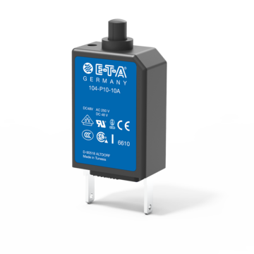
Thermal circuit breaker, integral type, single pole
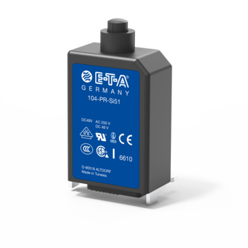
Thermal circuit breaker for pcb mounting, single pole
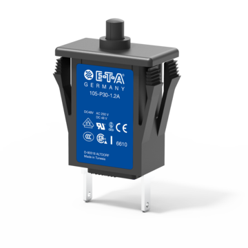
Thermal circuit breaker for snap-in mounting, single pole
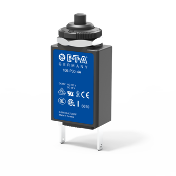
Thermal circuit breaker for threadneck panel mounting, single pole
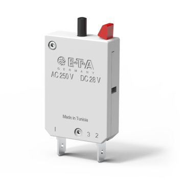
Thermal circuit breaker with manual release button, plug-in or snap in panel mounting
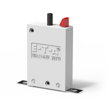
129-L11-H-KF
Thermal automotive circuit breaker with manual release, for base mounting
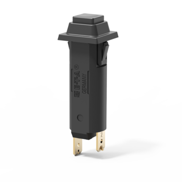
Push-push thermal switch/circuit breaker combination, single pole
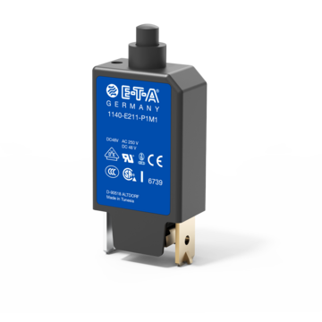
Single pole thermal circuit breaker, integral type
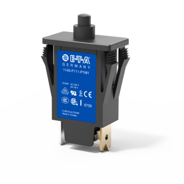
Thermal circuit breaker for snap-in panel mounting, single pole
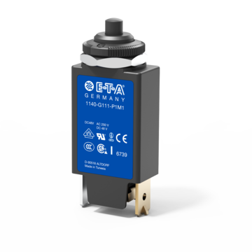
Thermal circuit breaker for threadneck panel mounting, double pole, one pole thermally protected
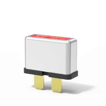
Thermal automotive circuit breaker with automatic reset function
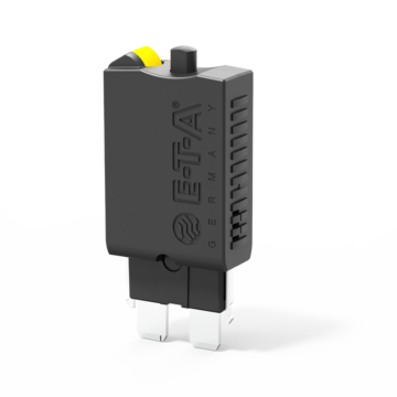
Miniaturised thermal automotive circuit breaker with colour-coded manual release
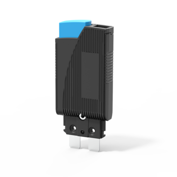
Thermal circuit breaker, plug-in type, single pole, switching function optional
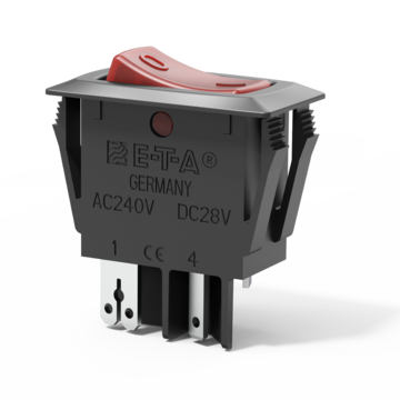
Thermal circuit breaker for snap-in panel mounting, rocker operated, fast acting
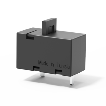
Miniaturised thermal circuit breaker for pcb mounting, fast acting
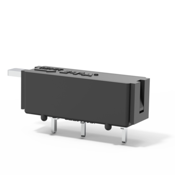
Miniaturised thermal circuit breaker for threadneck panel mounting, fast acting
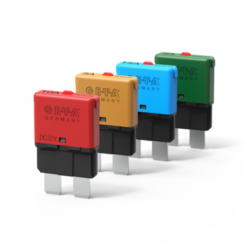
Automotive thermal circuit breaker, colour-coded housing, standard fuseblock mounting
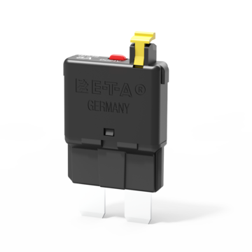
Automotive thermal circuit breaker with manual release option
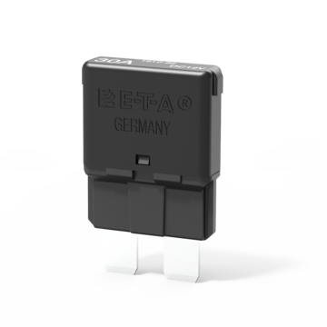
Automotive thermal circuit breaker with automatic reset function
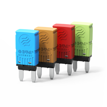
Single pole, thermal miniaturised circuit breaker designed for automotive applications
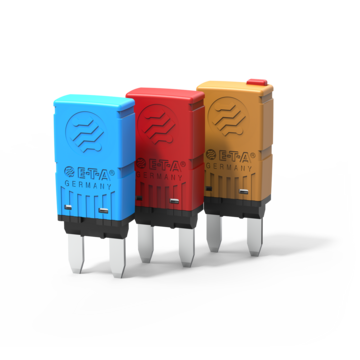
Single pole thermal reset circuit breaker in a miniaturised design intended for threadneck or snap-in mounting, dimensions: 32.0 x 27.0 x 13.6 mm.
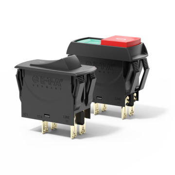
3120-N, thermal circuit breaker, snap-in mounting, 1-pole, 2-pole
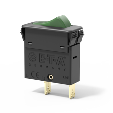
Thermal circuit breaker with rocker actuation, single, double or three pole
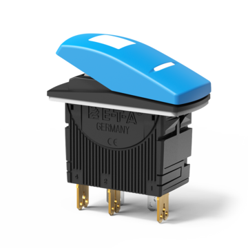
Thermal circuit breaker with rocker actuation, single pole, water splash protected (IP66)
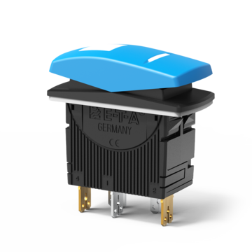
Single pole three-position switch, water splash protected (IP66)
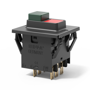
Thermal circuit breaker with push buttons, three pole
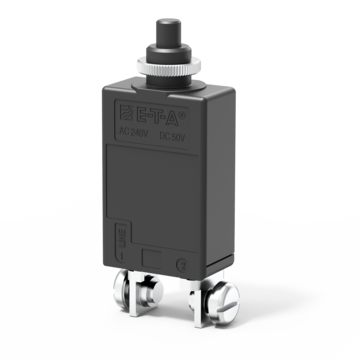
Thermal circuit breaker for threadneck panel mounting
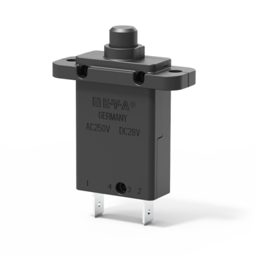
Thermal circuit breaker for flange mounting and manual release option
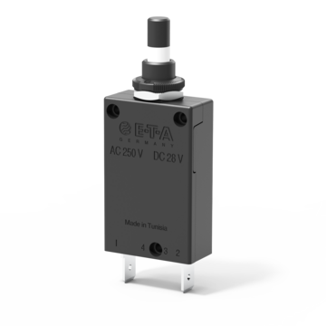
Thermal circuit breaker with threadneck, push-push actuation
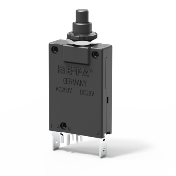
Thermal circuit breaker for threadneck panel mounting, with auxiliary contacts
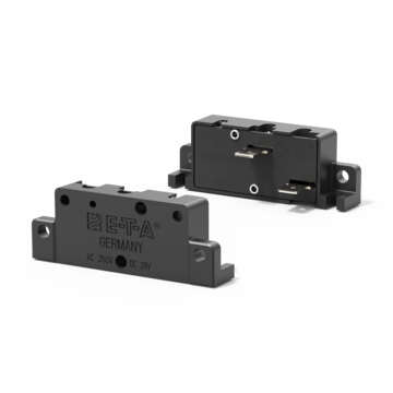
Single pole bimetal operated motor protection control, surface mounting, autoreset
Interactive Virtual Sample Kit
E-T-A's new interactive sample case features circuit breakers, relays, and power distribution modules. With the click of your mouse you can:
- Spin products with 360° CAD product viewer
- Filter products by attributes
- View product datasheets
- Add samples to a bag to request physical samples
Build your custom sample kit today
Fuse vs. circuit breaker: How to choose the right device for your application
Is a fuse or circuit breaker best for your design? Here are some pointers to help you decide. Three main factors go into choosing between circuit breakers and fuses: Convenience for the user, cost, and degree of protection. This white paper will give you guidance on what circuit protection device is best for your equipment.
Read White Paper

12 Most Common Mistakes When Specifying Circuit Protection for Equipment
It's only a circuit breaker. Yet there is enough complexity and confusion when it comes to specifying circuit protection that many engineers are designing equipment with too little or too much protection. Under protected circuits leave equipment vulnerable to damaging electrical surges. Over protected circuits add cost and can lead to nuisance tripping. Like Goldilocks and the three bears, the goal is to specify circuit protection that is "just right".
- International
Molded Case Circuit Breakers

Low Voltage Circuit Breakers
Automatic tripping devices.
Low Voltage Circuit Breaker is used for protection and open/close of electric circuit of low voltage circuit (1000VAC or less, 1500VDC or less).

MCCB will trip when overload or short-circuit occurred.
There are 3 types of Thermal-Magnetic Type, Hydraulic-Magnetic Type and Electronic Type.
Thermal-Magnetic Type

Trip with the power of bimetal and electromagnet.
- An overcurrent heats and warps the bimetal to trip by rotate the trip bar.
- If the overcurrent is excessive, movable core rotates clockwise and the armature is attracted and to trip by rotate the trip bar.
Hydraulic-Magnetic Type

Trip with the power of electromagnet.
- At an overcurrent flow, the magnetic force of the coil overcomes the spring, the core closes to the pole piece, attracts the armature, and actuates the trip bar. The delay is obtained by the viscosity of silicon oil.
- If the overcurrent is excessive, the armature is instantly attracted, without the influence of the moving core.
Principle of Electronic Trip Relay Operation

Trip with the calculation of electronic circuit.
- The current flowing in each phase is detected by a current transformer (CT). Each phase of the transformed current undergoes full-phase rectification in the rectifier circuit. After rectification, each of the currents are converted by a peak-conversion and an effective-value conversion circuit.
- When over current or short circuit current flows, each time-delay circuit generates a time delay corresponding to the largest phase. The trigger circuit outputs a trigger signal. The trip coil is excited, operating the switching mechanism to trip.
Especially, electronic type is very convenient for cooperation, as the rated current value is adjustable. By using optional setting device (Y-350), simple operation check and monitoring / setting of characteristic setting value are available.
Various connection methods such as Front connection type, Rear connection type, Plug-in type, etc. are available. You can order according to your needs.
Front connection type
Standard type connectable from the front.

Rear connection type
Wiring from the backside of the circuit breaker is available.

Plug-in type
Insert the main body into the plug-in terminal block.

- Hazard Categories and Special Symbols
- Please Note
- Related Documents
- Isolation Characteristics
- Unit-Mount Circuit Breaker Description
- Unit Mount Circuit Breaker Accessories
- Sealing Accessories
- I-Line Circuit Breaker Description
- I-Line Circuit Breaker Accessories
- PowerPact B Frame Ratings
Thermal Protection
Ac magnetic trip levels, dc magnetic trip levels.
- Temperature
- Extreme Atmospheric Conditions
- Electromagnetic Disturbance
- Overview of PowerPact B Insulation Accessories
- PowerPact B Insulation Accessories
- PowerPact B Equipment Installation Requirements
- Minimum Distances for Side-by-Side PowerPact B Installation
- PowerPact B Minimum UL Enclosure Volume
- Minimum PowerPact B Clearance Without Insulation Accessories
- Minimum PowerPact B Clearance with Interphase Barriers
- Minimum Clearance for PowerPact B with Long Terminal Shields
- Minimum Clearance for PowerPact B with Live Parts
- Minimum Clearance Between PowerPact B Backplate and Uninsulated Power Connectors
- PowerPact B Front Face with Toggle Handle
- Device Identification for PowerPact B with Toggle Handle
- Opening and Closing with the Toggle Handle
- Resetting with the Toggle Handle After a Trip
- Testing the Trip Mechanism with a Toggle Handle
- Locking Options for the Toggle Handle
- PowerPact B Front Face with Direct Rotary Handle
- Device Identification for PowerPact B with Direct Rotary Handle
- Opening and Closing with a Direct Rotary Handle
- Resetting with the Direct Rotary Handle After a Trip
- Testing the Trip Mechanism with a Direct Rotary Handle
- Locking Options for the Direct Rotary Handle
- Inserting Padlocks in the PowerPact B Rotary Handle
- Overriding the Rotary Handle Door Interlock
- PowerPact B Front Face with Front Extended Handle
- Device Identification for PowerPact B with Front Extended Handle
- Opening and Closing with the Front Extended Handle
- Resetting with the Front Extended Handle After a Trip
- Testing the Trip Mechanism with a Front Extended Handle
- Locking Options for the Front Extended Handle
- Inserting Padlocks in the Extended Rotary Handle
- Locking the Circuit Breaker with an Extended Rotary Handle in the O (OFF) Position When the Door is Open
- Overriding the Extended Rotary Handle Door Interlock
- PowerPact B Front Face with Side Rotary Handle
- Device Identification for PowerPact B with Side Rotary Handle
- Opening and Closing with the Side Rotary Handle
- Resetting with the Side Rotary Handle After a Trip
- Testing the Trip Mechanism with a Side Rotary Handle
- Locking Options for the Side Rotary Handle
- Inserting Padlocks in Side Rotary Handle
- Class 9421 Circuit Breaker Operating Mechanism
- Complete Kits for Class 9421 Operating Mechanism
- PowerPact B Front Face with 9421 Rotary Handle
- Device Identification for PowerPact B with 9421 Rotary Handle
- Opening and Closing with the 9421 Rotary Handle
- Resetting with the 9421 Rotary Handle After a Trip
- Testing the Trip Mechanism with a 9421 Rotary Handle
- Locking Options for the 9421 Rotary Handle
- Inserting Padlocks in the 9421 Rotary Handle
- Locking the Circuit Breaker with a 9421 Rotary Handle in the O (OFF) Position When the Door is Open
- Overriding the 9421 Door Interlock
- Class 9422 Circuit Breaker Operating Mechanism
- Complete 9422 Kits
- Class 9422 Flexible Cable Operating Mechanisms
- PowerPact B Front Face with 9422 Toggle Handle
- Device Identification for PowerPact B with 9422 Toggle Handle
- Opening and Closing with a 9422 Toggle Handle
- Resetting with the 9422 Toggle Handle After a Trip
- Resetting the 9422 Toggle Handle After a Trip Caused by an Electrical Fault
- Testing the Trip Mechanism with a 9422 Toggle Handle
- Locking Options for the 9422 Toggle Handle
- Overriding the 9422 Door Interlock
- Summary of Electrical Auxiliary Devices
- Slots for Electrical Auxiliary Devices
- Characteristics of PowerPact B Indication Contacts
- Operation of PowerPact B Auxiliary Indication Contacts
- PowerPact B-Frame Remote Electrical Trip
- List of Checks and Inspections
- A: Insulation Tests and Dielectric Strength Tests
- B: Temperature Rise Tests
- C: Inspect Switchboard
- D: Check Compliance with the Diagram
- E: Inspect Mechanical Equipment
- F: Check Mechanical Operation
- G: Clean Equipment
- Environmental and Operating Conditions
- Regular Preventive Maintenance
- Maintenance Operations Required
- Taking Precautions Before Responding to a Trip
- Identifying the Cause of the Trip
- Checking Equipment After a Trip
- Resetting the Circuit Breaker
- Repetitive Tripping
- Circuit Breaker Does Not Close
- PowerPact B DC Systems
- PowerPact B DC Wiring Diagrams
- Grounded B-Phase Systems (Corner-Grounded Delta)
- Indication Contacts
- Remote Operation (MN/MX Voltage Release)
For the best experience of this site, please enable Javascript for the www.productinfo.schneider-electric.com domain.
Thermal-Magnetic Protection for Circuit Breakers
Thermal-magnetic protection provides the following features for general-purpose applications:
Thermal protection against overload, with fixed threshold In.
Instantaneous protection against short circuits, with fixed threshold Ii.
The following figure shows the trip curve.
In Thermal protection pickup
Ii Instantaneous trip point
The thermal protection pick-up value cannot be adjusted. Its value for each frame rating is shown below.
The Time Current Curves (trip curves) provide the complete time-current characteristics of the circuit breaker when applied on an AC system. When applying thermal-magnetic circuit breakers on DC systems, they retain the same thermal tripping characteristics, but the magnetic trip levels vary. See table for the appropriate DC magnetic hold and trip levels.
Show QR code for this page
Was this helpful?
Contact Information
Legal information.
The information provided in this document contains general descriptions, technical characteristics and/or recommendations related to products/solutions.
This document is not intended as a substitute for a detailed study or operational and site-specific development or schematic plan. It is not to be used for determining suitability or reliability of the products/solutions for specific user applications. It is the duty of any such user to perform or have any professional expert of its choice (integrator, specifier or the like) perform the appropriate and comprehensive risk analysis, evaluation and testing of the products/solutions with respect to the relevant specific application or use thereof.
The Schneider Electric brand and any trademarks of Schneider Electric SE and its subsidiaries referred to in this document are the property of Schneider Electric SE or its subsidiaries. All other brands may be trademarks of their respective owner.
This document and its content are protected under applicable copyright laws and provided for informative use only. No part of this document may be reproduced or transmitted in any form or by any means (electronic, mechanical, photocopying, recording, or otherwise), for any purpose, without the prior written permission of Schneider Electric.
Schneider Electric does not grant any right or license for commercial use of the document or its content, except for a non-exclusive and personal license to consult it on an "as is" basis.
Schneider Electric reserves the right to make changes or updates with respect to or in the content of this document or the format thereof, at any time without notice.
To the extent permitted by applicable law, no responsibility or liability is assumed by Schneider Electric and its subsidiaries for any errors or omissions in the informational content of this document, as well as any non-intended use or misuse of the content thereof.
© 2018 – Schneider Electric
Uncategorized
Evolution of the molded case circuit breaker trip units and their value to customers.

Even though an 1879 patent filed by Thomas Edison provided a glimpse of the definition of what would become circuit breakers, fuses (use once and throw away) were the standard for the first 30-40 years in power distribution systems.1 In 1924, German inventor Hugo Stotz created and patented what was marketed as a re-settable fuse (Figure 1). It was a direct retrofit into common fuse panels of the day. The Stotz fuse incorporated a thermal element to detect and open contacts to clear overloaded or shorted circuits.2 This was a forerunner of the thermal-magnetic breaker (Figure 2) widely used in today’s power distribution systems.
How have circuit breakers evolved since the Stotz? More importantly, how can you take advantage of new circuit breaker technology to deliver to your clients a better tailored and user-friendly project? This brief article will focus specifically on the evolution of the breaker trip unit and the value this evolution provides to customers.
Circuit Breaker and Trip Unit
In order to understand what a trip unit is, let’s revisit the definition of a circuit breaker. A circuit breaker is a mechanical switching device designed to automatically detect and eliminate short circuits and overload current. A trip unit, specifically, is the “brain” of the circuit breaker as its function is to measure physical parameters such as electrical current and decide when to “trip” or rapidly open the mechanical contacts of the circuit breaker. At the bare minimum, a trip unit needs to offer overload and short circuit protection. In regard to the topic of evolution, the trip unit can be as simple as a bi-metallic strip, or now, as advanced as a computer. This evolution has opened the door to so much more than overload and short circuit protection – it’s opened a whole new world of protection, measurement, and control.
Let’s take a look at the evolution of the circuit breaker trip unit in four stages, starting with the basic thermal magnetic circuit trip unit, which is still the most widely used trip mechanism today.
Thermal Magnetic Circuit Trip Unit
The basic thermal magnetic circuit trip unit still provides a cost-effective solution for basic circuit protection and remains in widespread use. With the growth of critical electrical loads, the need for accurate and coordinated circuit protection has become much more important. However, the lower accuracy sensitivity offered by a thermal magnetic breaker cannot fully address this increasing demand. These shortcomings are amplified when you need breakers to trip in a coordinated fashion where only the problematic circuit is taken out of service. This is called selectivity and was a primary driver in the evolution from the thermal magnetic trip unit to the electronic trip unit which can provide a much higher degree of accuracy in sensing and responding to trip events.
Figure 3 exemplifies the typical response of a thermal magnetic breaker in the form of a time current curve (TCC). The X axis represents current and Y axis represents time, in seconds. The grid is logarithmic on both the X and Y axis. The breaker has two elements – ‘L’ or long time for the thermal, and ‘I’ for the magnetic. Note the width of the long-time element indicates a substantial lack of accuracy. Also note that the breaker’s response is significantly affected by temperature. There are two long time curve sections shown. The blue section is the ‘cold’ response and the orange section is the ‘hot’ response. The lack of accuracy makes coordination between thermal magnetic breakers difficult.
First Generation Electronic Trip Units
As noted earlier, this lack of accuracy, along with the growing need for coordinated circuit protection, drove the development of the electronic trip unit. First generation electronic trip units (Figure 4) were simple analog circuits comprised of resistors, capacitors, inductors, and transistors, however, they offered increased accuracy over their thermal magnetic cousins. Electronic trip breakers could be reasonably coordinated and be used to build a selectively coordinated distribution system.
Over the years, electronic trip units underwent incremental improvements including:
- Limited Adjustability – Provided ability to make basic adjustments to instantaneous and overload response to improve selectivity
- True RMS Sensing – Improved accuracy, bringing measurement much closer to the thermal response (not just looking at peak) of the current
- Thermal Memory – Ensured (even lacking the inherent “heater” present in original thermal magnetic breakers) that trip data could be retained and remembered for reporting
- Overall Improvement in Equipment Protection – Due to these enhancements which allowed more selectivity and eliminated the nuisance of premature trips which can damage the equipment
Modern Microprocessor Trip Units
As these electronic trip units continued to evolve, manufacturers used more and more sophisticated and integrated circuits which slowly evolved trip units into the modern microprocessor trip unit. The microprocessor trip unit provides even more improved protection accuracy and adjustability (ability to coordinate breakers closer together thus allowing additional breakers to operate in series IE levels of protection). Electronic trip unit breakers are commonly referred to as ‘LSI’ or ‘LSIG’ where ‘L’ is the long-time trip (60-600 sec), ‘S’ is the short time trip (0.1 to 60 sec), and ‘I’ is the instantaneous trip. ‘G’ is the optional ground fault trip. The ‘L’ and ‘S’ functions replace the thermal element in the thermal magnetic circuit breaker and the ‘I’ replaces the magnetic element. Figures 5 and 6 show the difference in response and adjustability between thermal magnetic and LSIG circuit breakers.
Figure 7 shows the time current curve of a typical breaker with a microprocessor LSI trip unit. Note the increased accuracy and adjustability in comparison with the thermal magnetic breaker.
This improved accuracy and adjustability of LSI breakers allowed for more advanced coordination of increasing layers of panels/circuit breakers in series.
Application Example
A building with a 2000A main switchboard and multiple power panels scattered throughout. Thermal magnetic breakers may allow up to three levels of coordination – switchboard main to switchboard feeder to power panel branch. Suppose the power panels were then feeding lighting panels. The lighting panel branch circuits can not be coordinated as it is the fourth level of coordination. If LSI breakers were used, the same system could be coordinated through the lighting panel and possibly with an additional panel in between (5 levels).
These evolving microprocessor trip units also provide much improved coordination with different types of protective devices such as motor starters, fuses, and relays, as well as the key ZSI (Zone Selective Interlocking) ability which allows planned overlap to gain maximum protection.
One big weakness that had yet to evolve was the advancement of sensors. So, while these electronic microprocessor trip units along with the right add-on equipment could provide early versions of metering from the circuit itself, the data was very inaccurate.
Today’s Advanced Next Generation Microprocessor Trip Units
Finally, we come to today’s advanced microprocessor trip units which are still microprocessor based, but because of the continued miniaturization in electronics to provide additional power, memory, and storage, and with a big change in sensor technology, these new breakers are a quantum leap ahead of their predecessors.
With the evolution of breaker trip units starting with basic overcurrent protection, you now have advanced capabilities that offer a host of additional protective functions nearly equal to functions offered by medium/high voltage multi-function relays. A few key features to look for include monitoring capabilities such as voltage, power quality, and even temperature of external sensors connected to the breaker.
Much of the new functionality is made possible by the replacement of the lower accuracy non-linear iron core current transformers with highly accurate linear current sensors. These sensors are based on the Rogowski coil concept. With traditional iron core current transformers, there is a tradeoff between measurement range and accuracy. Circuit breakers require sensing a large range of currents and accuracy is not as important. Today’s demands for metering require a smaller sensing range and much greater accuracy. The Rogowski coil sensor can cover a wide range of currents and has a very linear response. It is the perfect sensor for both protection and metering.
As mentioned, the real leap in value is moving so many functions “on board” the breaker trip unit that, in the past, could only be delivered by purchasing, integrating, and programming separate devices. A few examples (many more to explore) include:
- Built in programmable logic – Moves functions formerly available only through the addition of one or more PLCs, such as automatic source transfer, load shedding, load control, and generator control
- Communications – Standard network connections, additional communications technology such as IEC6185/GOOSE to high-speed breaker to breaker communications and coordination, including serving as a bridge between LV/MV applications.
- Metering – Ability to delivery revenue-class metering (typically 1% accuracy), harmonic measurement and reporting, and power quality monitoring
- Commissioning – Allows direct access to trip units via HMI panel (one panel for multiple breakers), or USB device (just copy over the settings), or even Bluetooth connection (outside the arc-flash zone)
The Evolution Will Certainly Continue
We’ve touched on the evolution of the circuit breaker trip unit across a century. Generally, three key technical advancements have opened up the possibilities of today’s advanced circuit protection with a molded case breaker – increased processor power (intelligence) due to advances in circuit board/component miniaturization, increased sensor accuracy as advances allowed for the application of the Rogowski coil for linear measurement, and the continued improvements to high-speed communications both in the processor capabilities and communication protocols. Overall, these three things combine to deliver the key cornerstone values required in smarter, safer, and more reliable power – accuracy plus the ability to make decisions and execute responses in milliseconds.
These capabilities will continue to evolve, and you and your customers will continue to benefit from the advancement of cheaper and more available raw computing power and communications over time.
- Friedel, R., & Israel, P. (1987). Edison’s electric light biography of an invention. New Brunswick, NJ, NJ: Rutgers Univ. Pr.
- Riemensperger, S. (2014, October 31). Miniature Breakers Stop Overloads, Short Circuits. Retrieved July 22, 2020, from com/conversations
- Electrical installation handbook – Protection, control and electrical devices (Sixth ed., ABB Technical Guide). (2010). Bergamo Italy: ABB SACE.
- Figure 3 – 3. (n.d.). In A Working Manual on Molded Case Circuit Breakers (Third ed.). Beaver, PA: Westinghouse Electric Corporation
Leave a Reply Cancel reply
Your email address will not be published. Required fields are marked *
Save my name, email, and website in this browser for the next time I comment.
- Circuit Breakers
- Molded Case Circuit Breakers
Record Plus™ Thermal Magnetic Trip
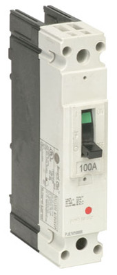
View Larger
Representative Image
Catalog No. : FBN16TE035RV
Description: 35A MCCB 1P 347V
UPC: 783164394122
Email page to others
- Email Address
Email Address (For your convenience, you can send the page to up to three e-mail addresses at a time. Your e-mail address will be shown in the forwarded message.)
Note: ABB will only use the e-mail addresses you provide to forward this page. ABB will not distribute or use the email addresses to contact your colleagues again.
Message Sent
Your message has been sent successfully.
We're sorry
Your e-mail can not be sent at this time. Please try again later.
Specifications
- Publications
Descriptors
Classifications, record plus types fc&fb - let through energy curves.
Publication No.: DES-031
Publication Type: Time Current Curves
Record Plus Types FC&FB - Peak Let Through Current
Publication No.: DES-030
- Skip to main content
- Skip to main navigation
- Skip to footer
Residential Thermal Magnetic Circuit Breakers
- Dapatkan alat bantu dan layanan produk kustom
- Akses pelatihan
- Kelola kasus dukungan
- Buat dan kelola pesanan Anda (hanya mitra resmi)
Selamat datang di Situs Web Schneider Electric

Circuit breaker, GoPact MCCB 250, 4 poles, 36kA at 415VAC, 250A rating, TMD trip unit, adjustable thermal protection
Poles description:
[In] rated current:
Breaking capacity:
Keberlanjutan

Kinerja kesejahteraan
Sertifikasi & standar.
REACh Declaration
Compliant with Exemptions
China RoHS declaration
Product out of China RoHS scope. Substance declaration for your information
Product Environmental Profile
The product must be disposed on European Union markets following specific waste collection and never end up in rubbish bins
End of Life Information

COMMENTS
Learn about the different types and functions of circuit breaker tripping units, such as thermal-magnetic, electronic, overload, short-circuit, ground-fault and fault-current protection. This article explains the basics of circuit breaker tripping units with diagrams and examples.
SACE Tmax XT is a range of MCCBs that offers extreme performance and protection features up to 1200 amps. It features thermal-magnetic, MCS, MCP and electronic trip units, embedded power metering, communications and logic, and easy integration and serviceability.
Thermal-magnetic molded case circuit breakers shown here are permanent trip UL Listed, CSA Certified, IEC rated, and also meet the requirements of Federal Specification W-C-375B/GEN as indicated in Digest Section 7. note. Consider using PowerPact™ circuit breakers for situations requiring circuit breaker accessories. ...
The second component used in a thermal magnetic circuit breaker is a thermal bimetallic strip that responds to prolonged low-level electrical surges or overloads of electrical currents. Excessive electrical currents will heat the bimetallic strip enough to bend it towards a trip bar that turns the circuit off.
A thermal magnetic circuit breaker combines two types of protection: instantaneous and time-delayed. It prevents fires and damage from excessive current, while allowing normal operation of devices with high inrush currents. Learn more about how it works and why you should choose it for your home or building.
Learn how a circuit breaker senses and responds to overload and short circuit conditions using a bi-metalic strip and a magnetic coil. The web page explains the trip mechanism, the manual trip button, and the overload and short circuit trips with diagrams and examples.
Learn how to read and interpret the trip curves of ABB low voltage circuit breakers, which comply with UL 489, UL 1066 and other standards. Find definitions, examples and specifications of thermal magnetic and electronic trip units.
The traditional molded-case circuit breaker uses electromechanical (thermal magnetic) trip units that may be fixed or interchangeable. An MCCB provides protection by combining a temperature sensitive device with a current sensitive electromagnetic device. Both these devices act mechanically on the trip mechanism.
The dependable, economical thermal-magnetic trip unit protects against overloads and short circuits, tripping to open the circuit and protect the conductors. ... When normal conditions are restored, the breaker can be closed to the ON position again. Circuit breakers reduce downtime and eliminate the need for fuse replacement. Versatility to ...
E-T-A offers a wide range of thermal circuit breakers for overload protection of motors, transformers, and other electrical systems. Learn about the technology, applications, and product comparison of thermal circuit breakers, and access datasheets, CAD, and white papers.
Learn about the types, principles and connection methods of low-voltage circuit breakers. Trip coil is a part of the electronic trip relay that operates the switching mechanism when overcurrent or short circuit occurs.
Learn how thermal-magnetic protection provides overload and short circuit protection for general-purpose applications. See the trip curves, pick-up values and DC trip levels for different frame ratings.
Molded Case Circuit Breakers Resolution: The thermal/mag has both thermal (for overload trip) and magnetic (for inrush/instantaneous trip) elements. This is used primarily for conductor protection. The mag only does not have thermal protection and is mainly used for motor protection. Released for: Schneider Electric USA
That is, unless it is a Motor Protection Circuit Breaker (MPCB), in which case you would have one additional dial that you set as the thermal trip point. MPCBs can only be used in motor circuits in a manner similar to a Manual Motor Starter, with the adjustable thermal trip acting as the Overload Protection.
Learn how LSIG circuit breaker trip units have evolved from thermal magnetic to electronic to microprocessor technology, and how they provide improved accuracy, adjustability, and coordination for circuit protection. See examples of time current curves and application scenarios for different types of trip units.
FB 100 circuit breakers are supplied with factory installed non-user interchangeable thermal-magnetic trip units and ca n be supplie d with o r wit hout l ugs. FB breakers are available in 1-, 2- and 3-pole versions. Record Plus½ product numbers ending in R or R0 do not include lugs. An R1 suffix indicates that the breaker is supplied with ...
Siemens offers one of most comprehensive lines of thermal magnetic circuit breakers. Various products are available to support every conceivable application in power distribution systems. Thousands of options including modular designs, molded cases or communication functionality enabling integration in system solutions.
Learn how thermal magnetic circuit breakers work with two switching mechanisms: bimetallic and electromagnetic switches. The magnetic portion of a standard circuit breaker is the electromagnet that responds to short circuits and trips the breaker.
Electrical current exceeding the breaker-overload rating heats the bimetal enough to bend it toward the trip bar. As the bimetal bends, it touches and rotates the trip bar to open the circuit.
For the longer-term thermal trip stage, the time is progressively longer depending on the level of excess current. If the current is only barely above the rated trip value, the breaker may take well over an hour to trip. However, the design requirements would prohibit the selection of a breaker that is nearly equal to the rated load current.
Schneider Electric Indonesia. G25F4A250 - Circuit breaker, GoPact MCCB 250, 4 poles, 36kA at 415VAC, 250A rating, TMD trip unit, adjustable thermal protection.