
Galvin Power is reader-supported. When you buy via our links, we may earn a commission at no cost to you. Learn more

How to Wire a Shunt Trip Breaker Wiring Diagram (DIY Guide)
Written by Edwin Jones / Fact checked by Andrew Wright
Table of Contents
Tools You Need
Step 1. install shunt trip accessory to the circuit breaker, step 2. installing shunt trip circuit breaker to the panel board, step 3. understanding the shunt trip breaker wiring diagram, step 4. start wiring the shunt trip circuit breaker to the safety control, step 5. checking or testing the installed unit.
Do you want to have an additional layer of protection for your home? Are you planning to install a shunt trip breaker in your home circuit? Are you looking for a how to wire a shunt trip breaker wiring diagram?
Yes, shunt trip breakers protect your home by cutting off power when activated manually or by your sensor. Although it’s not required, it ensures that power is switched off when the sensor is triggered. These sensors could be smoke detectors, fire alarms, or even a manual emergency stop button.
If you intend to add a safety system, I highly recommend reading through the steps below to know what to expect when installing this accessory.
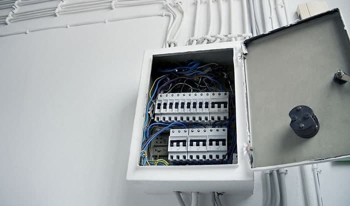
These are the tools and items you need to get started:
- Shunt trip accessory designed for your existing circuit breaker model .
- A circuit breaker is compatible with your shunt trip accessory if your current breaker isn’t compatible with any shunt trip accessories.
- An emergency stop switch if you want to install a kill-switch button.
- Screwdrivers of various tips and sizes as required in your electrical system
- A Shunt trip wiring diagram as your wiring guide
- Insulating gloves and eye protection
Not all circuit breakers accept shunt trip accessories. In fact, different breakers may require specific shunt trip accessory models. Some breakers also have a built-in shunt trip accessory—all you need is to wire and connect to your circuit to activate it.
Furthermore, some circuit breakers are only intended to have shunt trip accessories installed from the factory. So, before purchasing a shunt trip accessory, it’s highly recommended that you review what make and model of breaker you have. That way, you know what your options are before installation.
If you have a compatible system, you still need a shunt trip circuit breaker wiring diagram to ensure correct installation. However, do not just download any chart from the internet. For example, if you have a Square D branded circuit breaker, you need a Square D shunt trip breaker wiring diagram.
Before beginning installation, ensure that everything you need is within your reach. Also, always think of safety first!
Step-By-Step Guide to Wire a Shunt Trip Breaker Wiring Diagram

First, install the shunt trip accessory to your breaker. This procedure is pretty straightforward. Open your circuit breaker using a small flathead screw. Insert the insulator into its right place, and feed the wires in the holes near the shunt trip. Secure the shunt trip to its location, and put the cover back to the circuit breaker. And you’re done!
You can watch this video by Aaron CBIONE for a video guide on installing a shunt trip to the circuit breaker.
Note: Different makers have different installation processes. It’s best to refer to the manual guide provided in your circuit breaker.
Once the shunt trip accessory is connected to your circuit breaker, you need to connect it to your panel board as the main circuit breaker. Before installing this device, ensure that your system has no power.
If you’re not sure, it’s best to consult a professional electrician to avoid any accidents.
Once ready, open your panel board using your flathead screwdriver and plug in your shunt trip circuit breaker into the main power supply. Connect the mainline and the supply wire to the circuit breaker, then proceed to the next step.
Before wiring your shunt trip breaker to your safety control system or switch, you need first to understand its wiring diagram. This is a crucial part of the installation—that’s why you can’t skip it and need to be more careful with it.
Take a look at this recognizable wiring diagram made by Sikandar Haidar of Electriconline4u as a typical example.
Note: This sample diagram is simple and easy to follow. However, different systems may require other designs. Refer to the charts provided with the shunt trip, safety control system, or switch before starting. If you’re unsure, it’s best to consult a professional.
Using the sample above, connect one wire of the shunt trip to the neutral connection, then attach the other wire to the kill switch. Place a wire on the other side of the terminal of the kill switch through the supply connection.
With this, you now have a kill switch you can use to trip your electrical system’s main breaker quickly.
Pro Tip: Place the kill switch in an accessible area like near an emergency exit, so if a problem occurs, you can easily access it.
After installation, turn on or reconnect the power source to your main breaker panel . Flip the shunt trip circuit breaker on to begin testing your work.
To test your installation, press the kill switch. The shunt trip circuit breaker should immediately trip after pressing the kill switch. If it is not tripped, then there is something wrong with your installation.
Although not a requirement, having a shunt trip breaker in your residence provides an additional layer of safety. This is an excellent option if you have sensors in your building, like smoke detectors or fire alarms.
In case of emergencies, like flooding or sprinkler activation, you can also cut the power source by hitting the kill switch. This can prevent any shorts or accidental electrocutions because no power is supplied to your outlets.
So, what do you think of the installation process? Is it easy enough to DIY? Would you do this on your own? Remember to follow how to wire a shunt trip breaker wiring diagram. If you have any questions, feel free to reach out in the comments below.

I am Andrew Wright. With 8 years of experience designing, installing, and maintaining electrical power systems. I love my job, and I have always wanted to offer others the necessary help so they can take care of their houses.

- Circuit breakers
GE Shunt Trip Manual
- page of 4 Go / 4
Advertisement
Quick Links
Related manuals for ge shunt trip.

Summary of Contents for GE Shunt Trip
- Page 1 Lockout The catalog numbers for various voltage applications accessories, shown in Figures 1 and 2, can be installed are listed in Table 1 for the Shunt Trip and in Table 2 in 800-4000 ampere frame Power Break® II circuit for the Shunt Trip with Lockout.
- Page 2 Bell Alarm-Alarm Only or Bell A l a r m with Lockout accessories when a shunt trip occurs, The Shunt Trip accessory is installed in the accessory with the procedure described in the Accessory compartment through the front of the circuit breaker Configuration section.
- Page 3 Apply at least 55% of the rated ac voltage at least Lockout also change state. (The factory switch 75% of the rated de voltage to the Shunt Trip; the setting is disabled.) breaker should trip immediately. When an Undervoltage Release accessory causes...
- Page 4 Check that the accessory is Shunt Trip. completely inserted; reinsert if necessary. If a 1 2 Vdc Shunt Trip is installed, check that the polarity of the control power matches that shown on the label of the Shunt Trip accessory.
This manual is also suitable for:
Rename the bookmark, delete bookmark, delete from my manuals, upload manual.

Wire A Shunt Trip Breaker: Your Step-by-step Visual Guide
In the world of electrical engineering , dances with complex equipment are common. Few dances are as intricate as the one with the shunt trip breaker. As seasoned professionals, we guide you through this delicate ballet, ensuring your safety and the seamless operation of your electrical system.
Our comprehensive visual guide will demystify shunt trip breaker wiring, breaking down the process into manageable steps. By the end of this journey, you’ll possess the knowledge and skills to wire a shunt trip breaker with confidence.
First, let’s explore what a shunt trip breaker is and why it’s a crucial component in an electrical system.
Key Takeaways
- Shunt trip breakers are crucial in industrial settings and high-risk areas to prevent electrical fires and other hazards.
- The wiring diagram of a shunt trip breaker allows it to receive a signal from a separate source for immediate shutdown.
- The key parts of a shunt trip breaker include the coil, breaker mechanism, and trip unit, which work together to cut off power in case of overloads or faults.
- Proper installation and regular maintenance of shunt trip breakers are essential for ensuring system safety and efficiency.
Understanding the Importance and Functionality of Shunt Trip Circuit Breakers
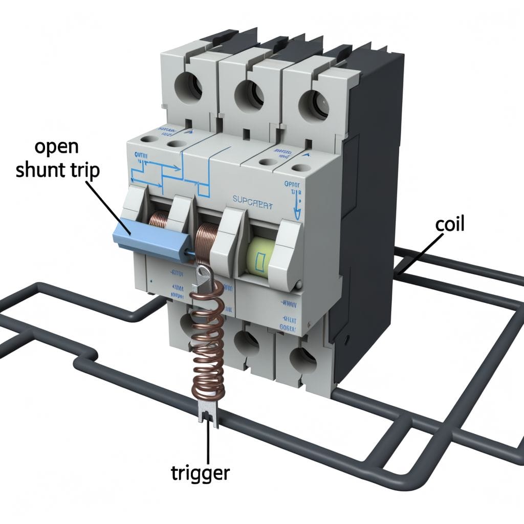
Diving into the heart of our discussion, it’s crucial to understand just what a Shunt Trip Circuit Breaker is. This innovative device shuts off an electrical circuit when it detects a problem, such as an overload or short circuit . This proactive functionality greatly reduces the risk of electrical fires and other potential hazards.
Its unique design allows the breaker to receive a signal from a separate source that triggers an immediate shutdown when necessary. This feature is particularly beneficial in environments where immediate circuit disconnection is paramount, like in industrial settings or high-risk areas.
Precision is key when installing a shunt trip breaker. A wrongly connected wire can compromise the breaker’s functionality, possibly leading to a dangerous situation. So, we strongly recommend professional installation to ensure the safety and efficiency of your electrical system.
Learning the Basics: Diagrammatic Representation of a Shunt Trip Breaker
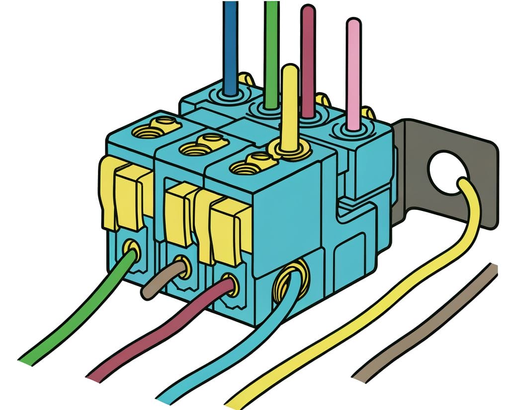
To grasp the workings of a shunt trip breaker, let’s delve into its diagrammatic representation. A shunt trip breaker is comprised of key parts like the coil, the breaker mechanism, and the trip unit. These parts work together to safely distribute electricity and prevent dangerous overloads.
The current first enters through the coil. When an electrical fault is detected, the coil becomes energized, triggering the trip unit. This in turn activates the breaker mechanism, causing the breaker to trip and cut off the power. It’s a simple and efficient system and serves as an innovative solution for electrical safety.
Detailed Steps to Wire a Shunt Trip Breaker Safely and Efficiently

Ready to wire a shunt trip breaker ? Start by preparing your workspace. Clear the area of any debris and make sure you have good lighting . Assemble your tools, which include a screwdriver, wire stripper, and multimeter.
Once your workspace is ready, follow the step-by-step process. Start by turning off the main power supply. After that, connect the shunt trip breaker to the circuit. Be sure to connect the wires correctly: the black wire to the breaker terminal, the white neutral wire to the neutral bus bar, and the green or bare ground wire to the ground bus bar.
Avoid common pitfalls like loose connections and incorrect wiring. Always double-check your work to ensure everything is wired correctly.
Connecting the Shunt Trip: An Essential Accessory for System Safety

A functioning shunt trip breaker represents an innovative approach to electrical safety. It automatically cuts power in the event of an electrical anomaly, shielding your system from damage. Hence, the importance of connecting the shunt trip can’t be overstated.
To wire a shunt trip breaker, we must employ a methodical approach. Connect the shunt trip coil to the breaker’s auxiliary terminal. Secure the connection using the recommended fasteners. Always test the shunt trip breaker to ensure it operates correctly and inspect the connection regularly for ongoing safety.
Troubleshooting Tips: Ensuring a Reliable Shunt Trip Breaker Connection
Even with careful installation, occasional challenges may arise in the wiring of a shunt trip breaker. To empower you further, let’s delve into troubleshooting tips for maintaining a reliable connection.
- Faulty Connections : If the shunt trip breaker isn’t functioning as expected, inspect the connections thoroughly. Ensure they are tight and secure. Reconnect any loose wires and tighten screws appropriately.
- Testing Procedures : Regularly test the shunt trip breaker using the recommended testing procedures. If the breaker fails to trip during a test, reassess the wiring and consult the manufacturer’s guidelines for troubleshooting.
- Voltage Issues : Check the voltage supply to the shunt trip breaker. Ensure it aligns with the specified requirements. Any discrepancies may affect the breaker’s performance. Consult a professional if voltage-related concerns persist .
- Visual Inspection : Periodically inspect the breaker for signs of wear, damage, or overheating. Replace any damaged components promptly. Visual cues can provide early warnings of potential issues.
- Interference and Environmental Factors : Assess the surrounding environment for potential interferences, such as electromagnetic interference or extreme temperatures. Shield the breaker from external factors that could compromise its functionality.
By familiarizing yourself with these troubleshooting techniques, you can address issues promptly, ensuring a reliable and efficient shunt trip breaker connection. Remember, a well-maintained breaker contributes significantly to the overall safety and reliability of your electrical system.
Are the Wiring Steps for a Shunt Trip Breaker Similar to a Water Well Pressure Switch?
No, the wiring steps for a shunt trip breaker are not similar to a water well pressure switch. While both involve wiring, the purpose and functionality of each are different. In the case of a shunt trip breaker, the wiring process will be specific to its functionality and requirements, and would not be interchangeable with water well pressure switch wiring .
In wrapping up, we’ve guided you through the crucial steps of wiring a shunt trip breaker. We trust you now understand its importance and how it operates.
With safety as our primary concern, we’ve shown you the right way to connect the shunt trip. Remember, knowledge is power, and this guide arms you with the needed expertise.
Keep exploring our guides for more practical electrical tutorials. Your safety and satisfaction are our top priorities.
Frequently Asked Questions
What is a shunt trip breaker.
A shunt trip breaker is a type of circuit breaker that can be triggered remotely to trip the breaker. It is frequently used in commercial kitchens, elevators, and other applications where the breaker needs to be tripped manually or remotely in case of an emergency.
Can you explain the shunt trip breaker wiring diagram?
The shunt trip breaker wiring diagram shows the connections for the shunt trip terminals, control circuit, and external power source. It also illustrates how the breaker is typically wired to trip the circuit breaker remotely or automatically during a surge or in case of an emergency such as a smoke alarm.
What is the purpose of a shunt trip breaker?
The main purpose of a shunt trip breaker is to provide circuit protection and to trip the breaker remotely or automatically during a surge, alarm, or emergency situation. It can help minimize equipment damage and ensure the safety of the electrical system.
How does a shunt trip breaker work?
A shunt trip breaker works by using an electromagnet to trip the breaker when it receives a signal from the control circuit. This can be done manually, through a relay, or remotely depending on the particular shunt trip accessories and model of the breaker.
What are the components of a shunt trip breaker?
A shunt trip breaker includes the main circuit breaker, shunt trip terminals, external power source, control system, and the shunt trip accessories. These components work together to trip the breaker manually or remotely in case of an emergency.
Similar Posts
What Are Boat Risers: Your Comprehensive Riser Guide
A chain is only as strong as its weakest link. In the realm of marine engines, this link…

Can’t Drive at Night Because of Lights: Safe Driving Guide
While we’d all love to possess the nocturnal prowess of an owl, the reality is that many of…

5 Best Motion Detector Lights: Illuminated Home With Security
When it comes to safeguarding your home, motion detector lights act as vigilant sentinels, casting a watchful eye…

5 Best Fluorescent Lights: Illuminate With Superior Glow
Illuminate your space with the 5 best fluorescent lights for superior glow: hykolity emits 4200 lumens, F8T5 provides…

2 Lights 1 Switch Power at Light: Electrical Run Made Easy
Just as a doctor uses a stethoscope to check a patient’s health, we use a Megger test to…

How Does a Cordless Kettle Work: Unveiling the Secrets
Have you ever wondered how your trusty cordless kettle operates without the constraints of a cord? You flick…
- Power System
- Electronics
- Telecommunications

Shunt Trip Circuit Breaker Wiring Diagram
Have you heard about the shunt trip circuit breaker? How will we draw the shunt trip breaker wiring diagram? We are acquainted with a circuit breaker that protects our power system from unwanted faults such as a short circuit.

Electricity is more ferocious than the leopard. A few days back, a leopard fell in death due to the flow of electricity. So, it’s very essential to develop a protection system with a view to avoiding an unwanted accident. A shunt trip circuit breaker is a vital solution in these circumstances. Let’s know the function & shunt trip breaker wiring diagram in a simple manner.
What is shunt trip breaker?
How do shunt trip breakers consume power, how does shunt coil work, shunt trip breaker wiring diagram and connection proceedure, how shunt trip breaker differs from regular circuit breaker.
This breaker is assembled with two basic parts:
- Shunt trip accessories
- Main circuit breaker part
Shunt trip accessories are attached to the main circuit breaker to protect the electrical system from any kind of undesired circumstances.
So, we can say that A shunt trip is an essential part of a circuit breaker that mechanically trips the breaker when power is applied to the shunt trip terminals. Now a question may arise, how do shunt trips consume power?
Shunt trip consumes power from an external power source. It doesn’t consume power from the circuit breaker cascaded with it.
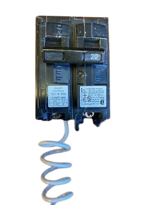
A shunt coil is used in the shunt trip breaker. It is used before the arrival of the relay. This shunt coil contains an electromagnet that is energized by an external power source and produces a magnetic field. There is a moveable bar that is attached to a spring for physical movement. The shunt trip moveable bar hits the tripping point of the circuit breaker internally and the breaker becomes off. In the MCCB circuit breaker, the tripping point is named “push to the trip”. While switching on the breaker and pushing this button the breaker becomes switched off and trip due to pushing this button. The shunt trip coil rod pushes this point internally when the shunt coil is operated. This will be more clear to u when I will discuss the shunt trip breaker wiring diagram.
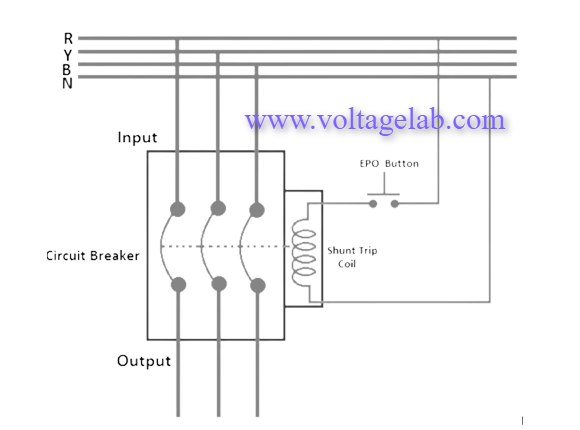
Please look at the above shunt trip breaker wiring diagram. A mentioning fact is that here the tripping coil in the MCCB is rated for 230V single-phase supply. Let’s discuss the connection procedure:
- At first we have to connect the neutral wire of the power supply to anyone terminal of the shunt trip coil. If its terminals are identified, then connect to the neutral terminal.
- Then we have to connect anyone terminal of the EPO (Emergency Push Off) button to any one phase of the power supply from the output of the MCCB.
- Finally, the rest terminal of the shunt trip coil should be connected with another terminal of EPO button. Connect another terminal of the EPO button.
- If the operating volt of the shunt coil is 220 volt, then we require to supply 220 volts to the shunt coil to operate or trip the breaker in a faulty time. So, our neutral will be connected directly to the shunt tripping coil, and the live line will be connected to the coil on another side through the EPO push-button switch normally open contacts.
- Ground fault breakers monitor the current on the neutral wire. On the other hand, shunt trip breakers can be tripped after energizing the shunt coil.
- Regular breakers utilize a relay for tripping purposes but shunt trip coil breakers use a shunt coil in this regard.
- GFCI (Ground Fault Circuit Interrupter) can’t be connected to a control circuit but shunt trip breaker is connected to control circuit.
Read More Articles
Introduction To Ice Cube Relay And Its Wiring Diagram
Discussion about Load Break Switch
We are expert engineers providing informative content. We need your support to make it the best. Your support is highly appreciated 🤗
- circuit breaker
- short circuit
- shunt coil tripping breaker
- shunt trip circuit breaker
How many Jobs are Best Paying Jobs in Electric Utilities Central?
3 phase indicator light wiring | voltage testing, 3 pole circuit breaker wiring diagram | mcb connection, most popular, choosing between lm339 and lm324 op-amps: an in-depth comparison, metal film resistors in surface mount technology, with prima power generators & custom power systems, the lights stay on, recent comments, editor picks, popular posts, popular category.
- Electrical 123
- Power System 33
- Electronics 25
- Substation 17
- Telecommunications 15

For business inquiries, collaboration, jointly work or want to say hi, Contact us by Email:
Contact us: [email protected]
© 2023 Voltage Lab. All rights reserved.
- Advertisement

- Electrical Repair
- Lighting Installation
- Hot Tub Wiring
- Emergency Electrical Service
- Ceiling Fan Installation
- Generator Installation
- Commercial Lighting Services
- Electrical Inspection
- What Is a Shunt Trip Breaker and How Does It Work
What Is a Shunt Trip Breaker and How Does It Work?
First things first: what is a shunt trip breaker? A shunt trip breaker is a specialized circuit breaker that is designed to remotely shut off power to a circuit in emergency situations, such as a fire or security breach. These breakers are commonly used in commercial and industrial buildings, as well as other facilities where safety is a top priority. In this article, we'll explore this type of breaker in detail and explain why hiring an electrical services provider for a wiring shunt trip breaker is essential.
The Many Benefits of a Shunt Breaker
Let’s recap: a shunt trip breaker is an electrical component connected to a circuit breaker and allows for remote operation through a schematic and AMP connection. Now that you know what a shunt trip circuit breaker is, it's time to move to the next part of this article: the benefits of using a shunt breaker.
- Remote Shut-Off: One of the main benefits of shunt breakers is that they can be remotely shut off in the event of an emergency. This allows them to quickly and easily disconnect power in a fire or other emergency, which can help prevent damage to the building and protect the occupants.
- Increased Safety: Besides remote shut-off, shunt trip circuit breakers provide an added level of safety and security by automatically shutting off power to a circuit in the event of an emergency. This helps prevent electrical fires and other hazards, protecting both people and property.
- Easy Installation: Shunt breakers are relatively easy to install and can be integrated into existing electrical systems, making it possible to retrofit older buildings with these devices.
- Cost-Effective: A shunt breaker is a cost-effective solution for increasing safety and security in commercial and industrial buildings. They are relatively inexpensive to purchase and install and can help prevent costly damage to the building and its contents in case of any emergency.
- Compatibility: Shunt breakers are compatible with a wide range of electrical systems and devices, making them a versatile and practical solution for increasing safety in various settings.
How Does a Shunt Trip Breaker Work?
A shunt trip breaker works by tripping the breaker when it receives a signal from an external device, such as a fire alarm or security system. This helps to prevent dangerous electrical fires or other hazards. When an emergency occurs, the external device sends a signal to the breaker, which causes the breaker to trip and open the circuit, interrupting the flow of electricity and preventing power from reaching the circuit, allowing for a quick and easy power disconnection.
Types of Shunt Trip Breakers
Now that you know the answer to "How does a shunt trip breaker work", it's time to discover about the two main types of shunt trip breakers.
- Manual Shunt Trip Breaker: This type of trip breaker requires manual intervention to reset the breaker after it has been tripped, meaning someone must physically go to the breaker and reset it after an emergency situation. This breaker is typically used in smaller residential buildings or situations where a dedicated staff member is available to reset the breaker.
- Automatic Shunt Trip Breaker: This type of breaker can automatically reset itself after being tripped and is typically used in larger buildings or in situations where there is not always someone available to reset the breaker. These breakers are often connected to fire alarm systems or other emergency management systems for auto-reset.
When is a Shunt Trip Breaker Required?
If you're wondering when is a shunt trip breaker required, know that it is required in any electrical system where there is a need to quickly and easily shut off power in the event of an emergency, such as a fire or security breach. Continue reading as we describe the importance of using shunt trip breakers and how to figure out which one you need to use for your building or facility.
The Importance of Using a Shunt Trip Breaker
- Shunt trip breakers automatically shut off power in emergencies.
- They prevent dangerous electrical fires and other hazards.
- They allow for quick and easy power disconnection in emergencies.
- They are easy to install and cost-effective solutions for increasing safety.
- They can be connected to fire alarm and emergency management systems.
- They ensure that the electrical system is in compliance with safety regulations.
- They are a versatile and practical solution for increasing safety in various settings.
Which Type of Shunt Trip Breaker to Use?
A manual breaker may be appropriate for a smaller building or in situations with a dedicated staff member available to reset the breaker, while an automatic breaker may be more appropriate for a larger building or in situations where someone is not always available to reset the breaker. Another option to consider is the use of a shunt trip relay, which can be used to trigger a shunt trip breaker remotely. These relays are typically connected to fire alarm systems or other emergency management systems and can send a signal to the breaker to trip it when an emergency occurs.
Shunt Trip Breaker Wiring Diagram
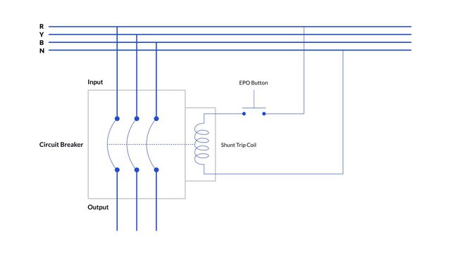
If you're wondering how to wire a shunt trip breaker, know that wiring can seem like a daunting task, but with the right knowledge and tools, it can be done relatively easily. Follow the steps below:
- Obtain a "How to wire a shunt trip breaker wiring diagram." (Check above).
- Gather necessary tools and materials such as wire strippers, nuts, and a voltage tester.
- Disconnect the power and wire the shunt breaker according to the instructions provided.
- Reconnect power to the circuit and test the breaker to ensure it works properly.
It is important to pay close attention to the diagram and follow the instructions carefully. This will ensure that the breaker is wired correctly and functions. Once the wiring is complete, you can reconnect the power to the circuit and test the breaker to ensure that it is working properly. It is always better to consult with a professional if you aren't confident about the wiring process.
What Does a Shunt Trip Breaker Do?
We hope by now you know what does a shunt trip breaker do, but here's a recap: a shunt trip breaker is a specialized circuit breaker that protects your house electrical systems from damage or hazards in emergencies. It works by tripping the breaker when it receives a signal from an external device, such as a fire alarm or security system, preventing dangerous electrical fires or other regular hazards.
Nevertheless, it is important to understand what does shunt mean in electrical terms and the role of electrical shunt trip breakers in commercial and industrial settings. Finally, to determine the appropriate type of breaker for your specific needs, it is best to consult an electrical services provider. If you're based in Colorado or surrounding areas, McCarrick Electric has got you covered.
Superior Electrical Solutions in Colorado
At McCarrick Electric, we have 25+ years of experience providing top-quality electrical services in Colorado. We value all of our customers, and that's why we offer a 15% discount for first-time residential clients and veterans. We take pride in our integrity, attention to detail, and cost-effectiveness. For more information, connect with us via our contact form or give us a call.
Latest Blog Entries

What to Do If Your Circuit Breaker Keeps Tripping?

Why Is Your Breaker Box Outside House? Here Are the Reasons
Why Won’t My GFCI Outlet Reset? How to Troubleshoot a GFCI Outlet

5 Ways to Prevent Short Circuits
- How to Control Motor From Two Places
- 220 Volt Single Phase Capacitor Start Motor Wiring Diagram
- Permanent Split Capacitor Motor Wiring Diagram
- Single Phase Motor Capacitor Start Capacitor Run Wiring Diagram
- Fridge Compressor Overheating And Shutting Off Problems And solutions
Electrical Online 4u – All About Electrical & Electronics
A platform to learn electrical wiring, single phase, 3 phase wiring, controlling, HVAC, electrical installation, electrical diagrams
Shunt Trip Breaker Wiring Diagram Explanation
As you know Safety is important in electricity works. Today I am writing about the shunt trip breaker wiring diagram which is related to the safety and protection of electricity. As you know that electricity is dangerous but it’s become more dangerous when it’s upgraded from 220 volts to 3 phase 440 volts. As you that mostly we use 3 phase system in industrial states where we can not protect our electrical distribution using RCD (residual current device). In Single phase wiring or house wiring, we use an electric power supply between phase and neutral which can be controlled by using a simple double pole RCD Breaker. But When it’s come to high-load places or where we use the three-phase supply then use an MCCB (module case circuit breaker) Shunt trip circuit breaker with an emergency push button switch which we know better with the name of EPO (emergency power off) button.
Shunt Trip Breaker Wiring Diagram with EPO Button.
In this post, I am just telling you about the wiring of a single EPO button with a shunt trip MCCB breaker. In an industrial state, the Electric operator’s duty is to operate the machinery and his duty is on the front of the Main panel board. Now if a short circuit is done in an electrical installation or other electrical accident, the operator can easily push a small push button switch and the all-electric power supply will be powered off. If we compare it with switching off the main circuit breaker then it will get more time.
Among the advantages of a shunt trip breaker, the most important thing is that we can install the emergency switch (EPO) anywhere, from where can easily push the button or where the push button is near to us.
One thing more is that we can install more than one EPO button for one breaker and every button will work the same. However, in this post shunt trip breaker wiring diagram I show only one EPO button and INSHALLAH in the next post I will show you the installation of multi EPO (emergency power off) buttons for a single shunt trip MCCB breaker.
Also, read below How do wire 3 or 4-pole MCCB Breakers? How to wire RCD Breaker? How earthing system works?
How Shunt Coil Work
In simple words, a shunt trip is an electromagnetic coil which makes a magnetic field by providing an external power source. In the coil a moveable rod is fixed with a spring and when we provide the supply The shunt trip moveable rod hit the tripping point or disconnecting point of the circuit breaker internally and the breaker becomes off or trips.
In the MCCB circuit breaker, we have a pushable button or place which is named “push to the trip” and when we switch on the breaker and push this button the breaker becomes switched off and trips due to pushing this button. The shunt trip coil rod pushes this point internally when the shunt coil is operated.
Here are some images of shunt coils and after that, we will discuss the shunt trip breaker wiring diagram with an image + symbol diagram.
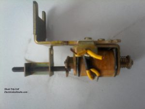
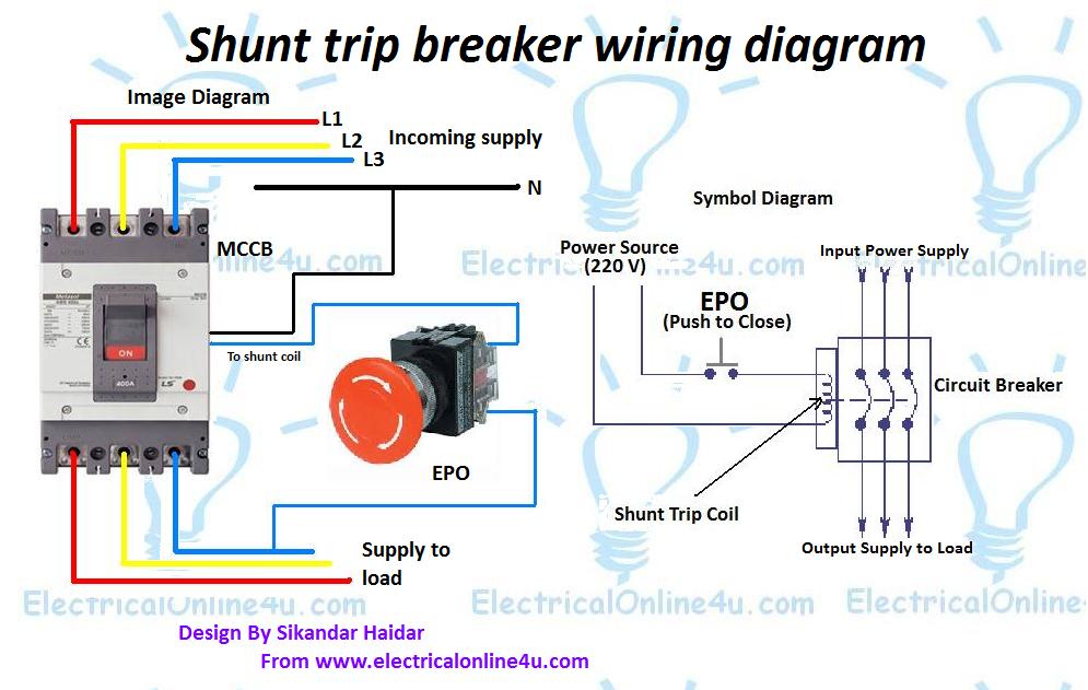
Now let’s how to wire the shunt trip device (accessory), it’s too simple as I have shown in the above shunt trip device images that a shunt coil has only two wires, just like a magnetic contactor or magnetic relay coil. But you must provide the power source regarding coil-rated volts. You can find out the rate coil label on the shunt coil, circuit breaker or on the shunt trip coil.
But the question is how to wire it. And the answer is that “it’s also too simple”. We use a push button switch for the shunt coil which we know by its short name “EPO” which I discuss in my above words. In the EPO switch, we have four terminals of which two are Normally close to each other and the other two are normally open. So we need to provide the supply / current to the shunt trip device circuit breaker when the emergency moments come.
I.e example ” if we have a shunt trip coil which operates on 220 volts, so we need to provide the 220 volts AC current to the shunt trip coil to operate or to trip the breaker in an emergency time. So our neutral will be connected directly to the shunt tripping coil and Phase (hot wire) will be connected to the coil another side through the EPO push button switch normally opens contacts.
So the EPO switch will be normally open and when we push the switch in emergency time the switch normally opens contacts will make a close contacts connection and the hot wire current start flowing to the coil and complete the circuit because the neutral wire current is already connected to the coil. So the coil will make a magnetic field and push the rod, the rod will press the trip point and the breaker will disconnect the power supply to load.
Here is the complete explanation of the shunt trip circuit breaker wiring diagram which helps you understand completely.
What is the purpose of a shunt trip circuit breaker
The main purpose of a shunt trip breaker is that we can easily switch off the main circuit breaker from our nearest place in a short time and can save us from electrical accidents.
Final words To wire, a shunt tripping breaker follows the below steps.
- First of all wire your Circuit breaker.
- Then connect the neutral wire to the shunt trip coil.
- Then connect the Phase (hot wire) to the EPO button normally open contact.
- Then get a connection from EPO to another side of the normally open contact and connect to the shunt trip coil.
- ← What’s Capacitor and Construction – Symbol Diagram
- How To Check Compressor Windings With Multimeter →
You May Also Like
3 Phase Manual Changeover Switch Wiring Diagram For Generator
Submersible Pump Control Box Wiring Diagram For 3 Wire Single Phase
What is ammeter and its uses in electric circuit, 3 thoughts on “ shunt trip breaker wiring diagram explanation ”.
Hi, I have a three phases circuit breaker, with 4 incoming cables and 4 cables to load (even the N cable is connected through the circuit breaker). Is it correct to connect the shunt trip to the phase and N in the load side of the circuit breaker?
thanks this is good blog. https://krmlight.com/shunted-vs-non-shunted/
One thing more that we can *install more *than* one EPO *button.
Leave a Reply Cancel reply
Your email address will not be published. Required fields are marked *
Save my name, email, and website in this browser for the next time I comment.
- Get custom product tools and services
- Access training
- Manage support cases
- Create and manage your orders (authorized partners only)
Schneider Electric USA Website
End of commercialization is the last date Schneider Electric will accept an offer for this reference. However, after Sales Services (repair, spare parts, etc.) will continue until its end of life.
Contact Customer Care Center - available 24 a day.

CIRCUIT BREAKER SHUNT TRIP 380-480V AC
Need more information check our technical faqs.
Easily find answers to the most frequently asked questions.

IMAGES
VIDEO
COMMENTS
The shunt trip opens the circuit breaker when its coil is energized by a voltage input (see Table 1). It is supplied with yellow and white ... 480 AC 408 - 528 168 - 288 N/A 50 600 AC 510 - 660 210 - 360 N/A 50 Table 3. Overcurrent Trip Switch Ratings. Control Voltage Frequency Contact Rating (Amperes) 250 50 - 60 Hz 10
Step-By-Step Guide to Wire a Shunt Trip Breaker Wiring Diagram. Step 1. Install Shunt Trip Accessory to the Circuit Breaker. Step 2. Installing Shunt Trip Circuit Breaker to the Panel Board. Step 3. Understanding the Shunt Trip Breaker Wiring Diagram. Step 4.
Overall, wiring a shunt trip breaker is quite simple and direct. Step 1: Get familiar with your shunt trip breaker's wiring schematic. It's crucial for a safe and correct installation. Step 2: Find the two screws on the shunt trip unit - these are where you'll connect your control circuit wires. Step 3: Attach the control circuit wires ...
Start your sales inquiry online and an expert will connect with you. Illustration: Wiring Diagram for QO/QOB/QOU Shunt Trip.
2. Catalog numbers and voltages for the Shunt Trip with Lockout. Operation. Apply control voltage to terminals. terminal strip on the right side of the breaker to trip. the circuit breaker. The Shunt Trip will. circuit breaker to trip when. greater than 75% o f the rated de voltage or 55% of the.
If mechanical check does not trip circuit breaker, see if shunt trip and intermediate plunger are correctly installed. If shunt trip and ... Accessory labels show connection diagram for shunt trip. Pigtail leads are color coded white and yellow. 2-9. Test cutoff switch. ... 480 336 0.07 525 0.07 550 0.08 600 0.1 1 0.05 24 2200 0.05 26
Once your workspace is ready, follow the step-by-step process. Start by turning off the main power supply. After that, connect the shunt trip breaker to the circuit. Be sure to connect the wires correctly: the black wire to the breaker terminal, the white neutral wire to the neutral bus bar, and the green or bare ground wire to the ground bus bar.
Welcome to our tutorial on wiring a Shunt Trip on QO™ Circuit Breakers. In this step-by-step guide, we'll walk you through the process of wiring a Shunt Trip...
Shunt Trip Accessory 1. Reset and turn circuit breaker ON. 2. Attach test circuit to accessory leads. When the test voltage reaches a minimum of 55 percent of the rated coil voltage, the circuit breaker must trip. 3. With breaker TRIPPED or OFF, check to make sure coil circuit has opened. Electrical Data For Shunt Trip Inrush Current
Connect the neutral wire to the neutral terminal, and the line wire to the line terminal. Make sure to tighten the screws securely to ensure proper electrical connection. Next, connect the shunt trip coil wires to the appropriate terminals on the circuit breaker. These wires are usually labeled as "Coil.".
Installation Instructions for Shunt Trip for R-Frame Series C Circuit Breakers and Molded Case Switches EATON CORPORATION www.eaton.com TABLE 1-1.SHUNT TRIP ELECTRICAL RATINGS DATA Averagecircuit breaker contact totalopening time approximately 62milliseconds,atrated voltage Endurance-500electrical operations.
The low energy shunt trip (LEST) (Fig. 1-1) is designed to interface with a customer ground fault detection circuit. The LEST consists of an intermittent-rated solenoid with a plunger and a reset lever assembled to a plug-in module. The plug-in mocule is mounted in slots in the top of the trip unit and occupies the accessory cavity in the ...
This video shows Shunt Trip Breaker Wiring Diagram. A shunt trip device is an optional accessory in a circuit breaker (MCCB) that mechanically trips the brea...
First, locate the control circuit terminals on the shunt trip breaker. These terminals are usually labeled "L1," "L2," and "L3." Connect the appropriate wires from the shunt trip unit to these terminals. Make sure to follow the wiring diagram provided with the shunt trip unit to ensure the correct connections.
Please look at the above shunt trip breaker wiring diagram. A mentioning fact is that here the tripping coil in the MCCB is rated for 230V single-phase supply. Let's discuss the connection procedure: At first we have to connect the neutral wire of the power supply to anyone terminal of the shunt trip coil.
A shunt trip breaker is a specialized circuit breaker that is designed to remotely shut off power to a circuit in emergency situations, such as a fire or security breach. These breakers are commonly used in commercial and industrial buildings, as well as other facilities where safety is a top priority. In this article, we'll explore this type ...
Step 3: Connect the Shunt Trip Wires. After removing the existing circuit breaker, it is time to connect the shunt trip wires to the GE shunt trip breaker. The shunt trip wires are typically color-coded and must be connected to the appropriate terminals on the breaker. It is important to follow the manufacturer's instructions for proper wiring.
Understanding the wiring diagram of this type of breaker is crucial for its proper installation and operation. The wiring diagram for a Square D Shunt Trip Breaker includes several components and their connections. It typically consists of a power source, a control circuit, and a shunt trip coil. The power source provides the necessary voltage ...
CASService explains how to wire a shunt trip breaker or contactor to an exhaust hood control package. For questions, please contact CASService at 1-866-784-6...
Today I am writing about the shunt trip breaker wiring diagram which is related to the safety and protection of electricity. As you know that electricity is dangerous but it's become more dangerous when it's upgraded from 220 volts to 3 phase 440 volts. As you that mostly we use 3 phase system in industrial states where we can not protect ...
The shunt trip is an essential safety feature that allows for remote shut off of the power to the elevator in case of an emergency or malfunction. The wiring diagram provides a visual representation of the electrical connections and components involved in the shunt trip system. It includes various elements such as circuit breakers, relays ...
A shunt trip breaker is a specially designed circuit to trip the mccb manually by the applied power supply to its shunt trip coil the main function of an mcc...
CIRCUIT BREAKER SHUNT TRIP 380-480V AC. S33038. Discontinued on: Feb 2, 2021. S33038 has not been replaced. Please contact your customer care center for more information. Product availability: Non-Stock - Not normally stocked in distribution facility. Contact sales Contact support Subscribe to the newsletter.